
Overview
Bently Nevada 330104-05-10-15-01-00 Migration-Ready Proximity Transducer for Legacy Control Systems
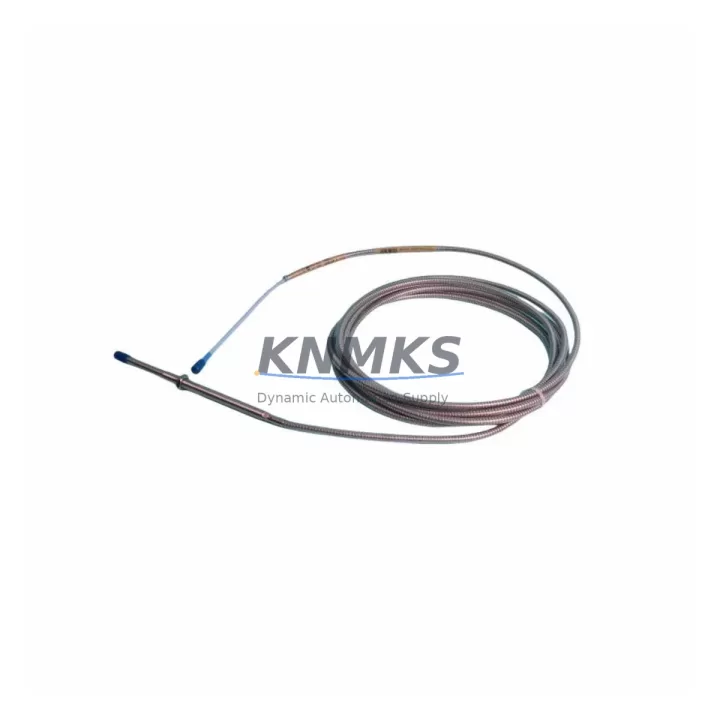
The Bently Nevada 330104-05-10-15-01-00 is an 8mm proximity transducer from the 3300 XL Series, engineered for continuous vibration and position monitoring in rotating machinery protection systems. As legacy Bently Nevada 3300 Series installations reach end-of-service milestones, this unit serves as the primary migration-ready replacement for discontinued 3300 standard-series transducers, enabling facilities to extend the operational life of their existing machinery protection infrastructure without a full system overhaul.
When planning a retrofit from an older 3300 standard transducer to the 330104-05-10-15-01-00, engineers must verify several critical parameters before committing to the swap. Power supply compatibility is the first checkpoint: the 3300 XL transducer system requires a –24 VDC supply, and the existing barrier or driver card must be confirmed to deliver adequate current within the specified range. Terminal wiring on the junction box or field terminal assembly should be inspected for correct shield grounding and cable routing, as improper shielding on long cable runs can introduce noise that triggers false alerts on the 3500 Series rack or legacy 3300 monitor cards.
Backplane interface and slot addressing are equally important. If the replacement is being installed alongside a Bently Nevada 3500/42M Proximitor I/O Module or a 3500/40M Proximitor Seismic Monitor, the channel address and rack configuration must be re-verified in the System 1 software or the legacy 3300 configuration utility. Transducer gap voltage—typically between –10 VDC and –18 VDC at the nominal air gap—should be measured and logged before and after installation to confirm the new unit is operating within the calibrated range for the specific target material.
For facilities running mixed-generation racks, the 330104-05-10-15-01-00 is commonly deployed alongside the Bently Nevada 330130-080-00-00 extension cable and the 330180-X0-05 Proximitor sensor to form a complete measurement chain. When the existing Proximitor is also being replaced, the entire chain—transducer, extension cable, and Proximitor—should be treated as a matched set to avoid sensitivity mismatches that can shift the overall scale factor and invalidate existing alarm setpoints. In installations where the 3500/22M Transient Data Interface is present, firmware version compatibility between the TDI card and the new transducer chain should be confirmed before energizing the loop.
HMI screen updates are a frequently overlooked step in transducer retrofit projects. If the facility uses a GE iFIX, Wonderware System Platform, or Rockwell FactoryTalk View SE display tied to the 3500 rack’s Modbus or OPC-DA output, the tag database and faceplate scaling values may need to be updated to reflect any change in the transducer’s sensitivity specification. Failing to update these values can result in displayed vibration readings that are offset from actual shaft displacement, creating a safety risk during post-maintenance run-up.
Installation space confirmation is straightforward for most 3300 XL retrofits: the 330104-05-10-15-01-00 uses the standard 8mm probe body diameter and is available in the 05-10-15-01-00 configuration specifying a 5-meter armored extension cable, making it a dimensional match for the majority of existing probe holders and conduit entries. However, if the original installation used a non-standard probe holder or a custom-machined bracket, the thread engagement depth and locknut clearance should be measured before ordering.
Commissioning and field calibration follow the standard Bently Nevada gap-setting procedure: with the machine at rest, the probe is adjusted to achieve the nominal gap voltage, the locknut is torqued to specification, and a static calibration check is performed using a calibrated gap simulator or a precision feeler gauge against a representative target material sample. Dynamic verification during slow-roll and trip speed confirms that the overall measurement chain is performing within the acceptance criteria defined in API 670.
Migration Compatibility Table
| Parameter | 330104-05-10-15-01-00 (3300 XL) | Legacy 3300 Standard Series | Retrofit Notes |
|---|---|---|---|
| Probe Diameter | 8 mm | 8 mm | Direct dimensional replacement; no probe holder modification required |
| Supply Voltage | –24 VDC | –24 VDC | Verify barrier/driver card current capacity before installation |
| Scale Factor | 7.87 V/mm (200 mV/mil) | 7.87 V/mm (200 mV/mil) | Confirm matched Proximitor; recalibrate if Proximitor is also replaced |
| Extension Cable | 5 m armored (330130-080-00-00 compatible) | 5 m standard | Use matched extension cable to maintain scale factor accuracy |
| Communication Protocol | Analog (4–20 mA / voltage output via Proximitor) | Analog | No protocol migration required; Modbus/OPC output unchanged at rack level |
| Monitor Compatibility | 3500/40M, 3500/42M, legacy 3300 monitors | 3300 monitors | Verify rack firmware version if using 3500 Series monitors |
| Installation Standard | API 670 5th Edition | API 670 4th Edition | Update alarm setpoints per API 670 5th Ed. after installation |
| Support terms | support terms confirmed by quotation | Covers manufacturing defects; includes pre-shipment functional test | |
Retrofit Planning for Existing Automation Systems
A successful retrofit of the 330104-05-10-15-01-00 into an existing machinery protection system begins with a thorough audit of the current installation. The field wiring from the probe tip to the junction box should be inspected for insulation integrity, especially in high-temperature or high-vibration environments where cable jackets degrade over time. If the existing extension cable shows signs of wear, replacing it with a new 330130-080-00-00 armored extension cable at the same time as the transducer eliminates a common source of post-retrofit signal anomalies.
At the rack level, the 3500/42M Proximitor I/O Module channel configuration should be exported from the rack configuration software before any hardware changes are made. This backup preserves the existing alarm setpoints, danger setpoints, and OK relay logic, allowing the configuration to be restored quickly if the retrofit requires a rack power cycle. If the facility is also upgrading from a legacy 3300 monitor card to a 3500 Series rack, the I/O module slot assignment and the system power supply module—such as the 3500/15 Power Supply—must be sized to support the additional current draw of the new transducer chain.
In control cabinets where space is constrained, the compact form factor of the 3300 XL probe body simplifies installation. However, if the retrofit is part of a broader control cabinet upgrade that also includes replacing a legacy PLC I/O module or adding a new signal isolator for the vibration output, the overall cabinet thermal load and DIN rail space should be recalculated. Signal isolators are frequently added during these projects to provide galvanic isolation between the 3500 rack analog outputs and the plant DCS or safety instrumented system inputs, protecting both systems from ground loop interference.
For facilities that are simultaneously migrating their communication infrastructure from legacy serial Modbus RTU to Ethernet-based Modbus TCP or OPC-UA, the 3500 rack’s communication gateway module should be configured and tested independently of the transducer retrofit to avoid conflating two separate sources of potential commissioning issues. Keeping the transducer replacement and the communication protocol migration as sequential, independently verified steps is the most reliable approach to minimizing overall project risk.
Downtime Control During System Migration
Minimizing unplanned downtime during a transducer retrofit requires a structured pre-outage preparation process. Before the maintenance window opens, the replacement 330104-05-10-15-01-00 unit should be bench-tested using a calibrated gap simulator to verify that the output voltage at the nominal air gap falls within the specified range. This pre-shipment functional verification—which is included as standard practice for all units supplied through KNMKS—confirms that the replacement unit is ready for immediate installation without additional bench calibration time on-site.
The original program logic in the connected PLC or DCS should be backed up and version-controlled before the maintenance window. If the vibration monitor’s OK relay output is wired into the plant safety interlock system, the interlock should be placed in bypass mode through the proper management-of-change procedure before the transducer is removed, preventing a spurious trip during the gap-setting procedure. Once the new transducer is installed and the gap voltage is confirmed, the interlock bypass should be removed and the system returned to normal protective mode before the machine is restarted.
Post-installation, a slow-roll data capture using the System 1 software or a portable data collector confirms that the new transducer chain is producing clean, noise-free signals before the machine is brought up to operating speed. Any unexpected DC offset or AC noise component at this stage should be investigated and resolved before the machine reaches trip speed, as these anomalies are far easier to diagnose at slow-roll than at full operating speed. Documenting the as-left gap voltage, slow-roll vibration level, and overall gain factor provides a baseline for future predictive maintenance trending.
By following this structured approach—pre-shipment testing, pre-outage backup, controlled bypass of safety interlocks, gap setting, slow-roll verification, and as-left documentation—facilities can typically complete a single-channel transducer retrofit within a two-to-four hour maintenance window, keeping production impact to a minimum while ensuring the integrity of the machinery protection system.
Retrofit Support FAQ
Q: Is the 330104-05-10-15-01-00 a direct drop-in replacement for the legacy Bently Nevada 3300 standard 8mm transducer?
A: Yes. The 3300 XL 8mm probe body is dimensionally compatible with existing probe holders designed for the standard 3300 8mm series. The scale factor and supply voltage are identical, so existing alarm setpoints remain valid provided the Proximitor sensor is also a matched 3300 XL unit. If the existing Proximitor is a legacy 3300 standard model, it should be replaced simultaneously to maintain measurement chain accuracy.
Q: What wiring changes are required when installing the 330104-05-10-15-01-00 into an existing 3500 Series rack?
A: No wiring changes are required at the rack terminal block if the existing field wiring is in good condition and the cable length is within the specified range for the 5-meter extension cable configuration. The terminal assignments for the probe, extension cable shield, and Proximitor output are identical to the legacy 3300 standard series. A continuity and insulation resistance check of the existing field cable is recommended before reusing it with the new transducer.
Q: How is the unit tested before shipment, and what documentation is provided?
A: Every 330104-05-10-15-01-00 unit supplied by KNMKS undergoes a pre-shipment functional test that verifies output voltage at the nominal air gap, supply current draw, and cable continuity. A test report is available upon request. All units are covered by a support terms confirmed by quotation against manufacturing defects from the date of shipment. In-stock units are typically available for same-day or next-business-day dispatch.
Q: Can this transducer be used in a system that is being migrated from a 3300 monitor to a 3500 Series rack?
A: Yes. The 330104-05-10-15-01-00 is fully compatible with both the legacy 3300 monitor cards and the current 3500/40M and 3500/42M monitor modules. During the rack migration, the transducer and its matched Proximitor can remain in service on the legacy 3300 monitor while the new 3500 rack is being configured and tested in parallel, allowing a hot-cutover approach that minimizes the period during which the machine operates without vibration protection.
© 2026 KNMKS. All rights reserved.
Original Source: https://knmks.com
Contact: admin@knmks.com | +86 18359268345
Product Identification
- Brand / Ecosystem
-
Bently Nevada
Bently Nevada - Model / Series
-
330104-05-10-15-01-00
Bently Nevada 3300 XL / 3301 Series - Product Family
- Sensors
- Availability Status
- Available on request after model and quantity confirmation
- Inquiry Type
- B2B RFQ, replacement inquiry and project spare-part request
- Pre-Quote Check
- Exact SKU, brand, series, quantity, nameplate photos and destination country are checked before quotation
System Path
Where this product fits in the KNMKS automation structure.
Specification & Inquiry Focus
- Sensor range
- Photoelectric, proximity and process sensors
- Common needs
- Output type, distance and connector
- Project support
- Machine detection and replacement inquiry
Buyer Confirmation
Information KNMKS checks before replying.
- Exact model
- 330104-05-10-15-01-00
- Brand / ecosystem
- Bently Nevada
- Product family
- Sensors
- Application note
- Replacement, maintenance, project build or spare-part list
- Useful photos
- Nameplate, installed unit, cabinet layout or connector side
- Delivery details
- Quantity, destination country and target schedule
Document Support
Files and notes can be confirmed during quotation.
- Product photos or nameplate confirmation when available
- Packing and delivery notes before quotation confirmation
- Support scope and delivery terms confirmed per inquiry
- Export document coordination for qualified B2B requests
Inquiry Support
- NPN/PNP, analog and digital output checking
- Connector and cable compatibility review
- Fast inquiry support for maintenance teams
What to Send Us
- Brand and exact model number: Bently Nevada 330104-05-10-15-01-00
- Quantity and required delivery time
- Application, replacement requirement or nameplate photo
- Destination country and shipping preference
RFQ Preparation
This is a product inquiry page built for RFQ communication.
Fast Model Check
Send this model to KNMKS for confirmation.
Include quantity, destination country and photos if this is a maintenance replacement. The inquiry will be saved with a reference number after submission.
Brand & Compatibility Note
KNMKS displays automation product information for well-known industrial brand ecosystems and compatible replacement references. Brand names are used for product identification and compatibility reference only; final availability and commercial terms are confirmed per quotation.
 Manufacturing
 Machine Tools
 Packaging
 Energy & Power



 PLCs & Controllers
 HMI & Displays
 Servo Systems
 Variable Frequency Drives