
Overview
Bently Nevada 330104-05-10-10-02-CN 3300 XL Transducer: Migration-Ready Replacement for Legacy Vibration Monitoring Systems
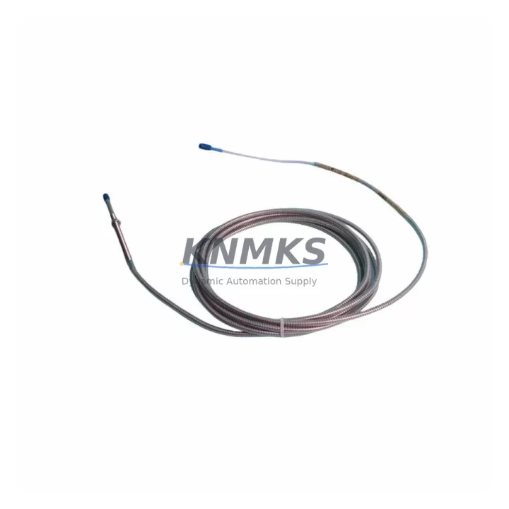
The Bently Nevada 330104-05-10-10-02-CN is a high-precision eddy-current proximity transducer engineered for the 3300 XL Series vibration monitoring platform. As aging DCS and machinery protection systems approach end-of-life, this transducer serves as a direct, migration-ready replacement for obsolete or discontinued proximity probes in rotating machinery applications including turbines, compressors, pumps, and gearboxes. Whether you are executing a full control system modernization or performing targeted spare-part substitution to extend the operational life of an existing installation, the 330104-05-10-10-02-CN delivers verified electrical and mechanical compatibility with the 3300 XL monitor rack architecture.
Facilities managing legacy Bently Nevada installations frequently encounter the challenge of sourcing discontinued proximity transducers that match the original signal conditioning chain. The 330104-05-10-10-02-CN addresses this directly: it maintains the standard 5-metre integral cable configuration, the -24 VDC bias voltage requirement, and the 200 mV/mil (7.87 V/mm) scale factor that the 3300 XL Series monitor cards — including the 3300/16 and 3300/20 — expect at their input terminals. This eliminates the need to recalibrate monitor setpoints or modify existing alarm and trip thresholds during the swap-out procedure.
Migration Compatibility Table
| Parameter | 330104-05-10-10-02-CN | Legacy / Replaced Models |
|---|---|---|
| Series Platform | Bently Nevada 3300 XL | 3300 Series (pre-XL) |
| Cable Length | 5 m (integral) | 5 m standard |
| Probe Tip Diameter | 10 mm | 10 mm |
| Thread Size | 10-32 UNF | 10-32 UNF |
| Scale Factor | 200 mV/mil (7.87 V/mm) | 200 mV/mil |
| Bias Voltage | -24 VDC nominal | -24 VDC |
| Linear Range | 0.25 – 2.25 mm | 0.25 – 2.25 mm |
| Communication / Signal | Analog (eddy-current) | Analog (eddy-current) |
| Monitor Card Compatibility | 3300/16, 3300/20, 3300/25 | 3300/16, 3300/20 |
| Installation Clearance | Standard probe boss / bracket | Same |
| Firmware / Configuration | No firmware; hardware transducer | No firmware |
| Retrofit Recommendation | Direct drop-in replacement | Verify gap voltage at commissioning |
| Commissioning Focus | Gap voltage, cable routing, connector seating | Same procedure applies |
| Support terms | support terms confirmed by quotation — all units tested prior to shipment | |
Retrofit Planning for Existing Automation Systems
A successful retrofit begins well before the maintenance window opens. When integrating the 330104-05-10-10-02-CN into an existing 3300 XL rack, engineers should first audit the Proximitor® / Seismic Monitor housing — typically a 3300/55 or 3300/65 Proximitor — to confirm that the extension cable assembly (such as the 330130-045-00-00 or 330130-080-00-00 series) is undamaged and correctly terminated at the junction box. The extension cable is the most common point of signal degradation in long-running installations, and replacing only the probe while leaving a compromised extension cable in place will produce erratic gap voltage readings that mimic a faulty transducer.
Within the monitor rack itself, verify that the 3300/16 or 3300/20 monitor card’s channel configuration has not drifted from the original commissioning record. The Rack Interface Module (RIM) — often a 3300/10 or 3300/46 — manages communication between the monitor cards and the plant DCS or safety system. If the facility is simultaneously upgrading from a legacy Modbus RTU link to a more modern communication path, the RIM firmware and the DCS I/O mapping should be validated before the transducer swap to avoid masking a pre-existing communication fault behind a hardware change.
For installations where the control cabinet also houses a 3500 Series rack alongside the 3300 XL system, pay particular attention to power supply loading. The 3500/15 Power Supply Module and the 3300 XL internal power supply each have defined current budgets; adding or replacing transducers changes the aggregate load on the -24 VDC rail. Confirm that the total transducer count per power supply remains within the manufacturer’s rated capacity before energizing the new probe. Similarly, if the retrofit scope includes adding I/O expansion — for example, integrating a new thermocouple or 4–20 mA pressure input alongside the vibration channel — coordinate the I/O address assignments in the monitor configuration software before the outage to minimize on-site programming time.
Where HMI screens display real-time vibration trend data sourced from the 3300 XL channels, update the tag database to reflect any channel renumbering that may result from rack reorganization. Failure to synchronize HMI tag assignments with the physical channel map is a common source of post-retrofit alarm confusion that extends commissioning time unnecessarily.
Downtime Control During System Migration
Minimizing unplanned downtime during a proximity transducer replacement requires a structured pre-outage preparation protocol. Before isolating the measurement point, export and archive the current monitor configuration — including alarm setpoints, danger thresholds, time-delay settings, and channel inhibit states — from the 3300 XL configuration software. This archived configuration serves as both a restoration baseline and a commissioning verification checklist.
During the physical swap, maintain the original cable routing and conduit path to preserve the electromagnetic shielding integrity of the signal circuit. Re-use existing cable clamps and support brackets where possible; unsupported cable runs introduce mechanical resonance that can corrupt vibration measurements at high shaft speeds. After seating the new 330104-05-10-10-02-CN probe at the correct gap — typically 1.0 to 1.5 mm from the shaft surface, yielding a bias voltage of approximately -10 to -12 VDC — verify the gap voltage at the monitor card input before restoring the channel from inhibit.
Restore alarm and trip functions in a defined sequence: first confirm the OK relay status on the monitor card, then re-enable the channel in the DCS logic, and finally release any bypasses in the Safety Instrumented System (SIS) if the vibration channel feeds a safety function. This sequenced restoration prevents nuisance trips during the brief period when the new transducer is settling to its steady-state gap voltage. Total planned downtime for a single-channel transducer replacement, when pre-outage preparation is complete, should not exceed two to four hours for a practiced maintenance team.
Retrofit Support FAQ
Q1: Is the 330104-05-10-10-02-CN a direct replacement for earlier 330104 series probes without the -CN suffix?
A: The -CN suffix designates the connector type used on the probe body. In most 3300 XL installations the connector mates directly with the standard extension cable assembly. However, if your existing extension cable terminates in a different connector style, a field-installable adapter or a replacement extension cable from the 330130 series may be required. Confirm the connector configuration against your as-built drawings before ordering.
Q2: What pre-shipment testing is performed on each unit?
A: Every 330104-05-10-10-02-CN unit undergoes electrical continuity verification, scale factor confirmation, and bias voltage output testing prior to shipment. A test report is available upon request. All units are covered by a support terms confirmed by quotation from the date of shipment.
Q3: Can this transducer be used with a 3500 Series monitor rack instead of the 3300 XL?
A: The 330104-05-10-10-02-CN is designed and characterized for the 3300 XL platform. While the physical probe dimensions are similar to transducers used with the 3500 Series, the 3500 rack uses a different Proximitor driver circuit and scale factor verification process. Cross-platform use requires explicit compatibility confirmation from the system integrator and re-characterization of the transducer-driver pair.
Q4: What is the typical lead time and do you maintain stock?
A: We maintain inventory of the 330104-05-10-10-02-CN to support urgent replacement and planned maintenance schedules. Standard orders ship within 1–3 business days. For large-quantity orders or scheduled outage kits, contact admin@knmks.com or call +86 18359268345 to confirm availability and arrange priority dispatch.
© 2026 KNMKS. All rights reserved.
Original Source: https://knmks.com
Contact: admin@knmks.com | +86 18359268345
Product Identification
- Brand / Ecosystem
-
Bently Nevada
Bently Nevada - Model / Series
-
330104-05-10-10-02-CN
Bently Nevada 3300 XL / 3301 Series - Product Family
- Sensors
- Availability Status
- Available on request after model and quantity confirmation
- Inquiry Type
- B2B RFQ, replacement inquiry and project spare-part request
- Pre-Quote Check
- Exact SKU, brand, series, quantity, nameplate photos and destination country are checked before quotation
System Path
Where this product fits in the KNMKS automation structure.
Specification & Inquiry Focus
- Sensor range
- Photoelectric, proximity and process sensors
- Common needs
- Output type, distance and connector
- Project support
- Machine detection and replacement inquiry
Buyer Confirmation
Information KNMKS checks before replying.
- Exact model
- 330104-05-10-10-02-CN
- Brand / ecosystem
- Bently Nevada
- Product family
- Sensors
- Application note
- Replacement, maintenance, project build or spare-part list
- Useful photos
- Nameplate, installed unit, cabinet layout or connector side
- Delivery details
- Quantity, destination country and target schedule
Document Support
Files and notes can be confirmed during quotation.
- Product photos or nameplate confirmation when available
- Packing and delivery notes before quotation confirmation
- Support scope and delivery terms confirmed per inquiry
- Export document coordination for qualified B2B requests
Inquiry Support
- NPN/PNP, analog and digital output checking
- Connector and cable compatibility review
- Fast inquiry support for maintenance teams
What to Send Us
- Brand and exact model number: Bently Nevada 330104-05-10-10-02-CN
- Quantity and required delivery time
- Application, replacement requirement or nameplate photo
- Destination country and shipping preference
RFQ Preparation
This is a product inquiry page built for RFQ communication.
Fast Model Check
Send this model to KNMKS for confirmation.
Include quantity, destination country and photos if this is a maintenance replacement. The inquiry will be saved with a reference number after submission.
Brand & Compatibility Note
KNMKS displays automation product information for well-known industrial brand ecosystems and compatible replacement references. Brand names are used for product identification and compatibility reference only; final availability and commercial terms are confirmed per quotation.
 Manufacturing
 Machine Tools
 Packaging
 Energy & Power



 PLCs & Controllers
 HMI & Displays
 Servo Systems
 Variable Frequency Drives