
Overview
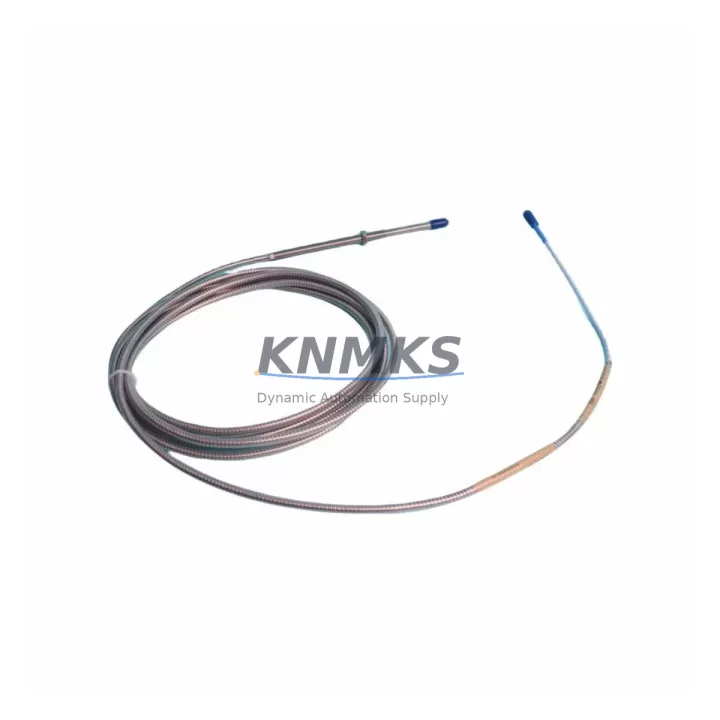
Bently Nevada 330104-01-17-05-01-CN 3300 XL Spare Part: Maintenance-Proven Proximity Transducer for Factory Uptime
The Bently Nevada 330104-01-17-05-01-CN is an 8mm proximity transducer engineered for the 3300 XL Series vibration monitoring system — one of the most widely deployed machinery protection platforms in rotating equipment facilities worldwide. Whether you are managing a planned annual overhaul, responding to an unscheduled shutdown, or building a strategic spare parts inventory for your control room, this transducer delivers the measurement accuracy and long-term reliability that maintenance engineers and procurement teams depend on.
Designed to work within Bently Nevada’s 3300 XL proximity system architecture, the 330104-01-17-05-01-CN operates as part of a three-component loop: the transducer itself, a compatible extension cable (such as the 330130 series), and a signal conditioner or proximitor module (such as the 3300 XL 8mm proximitor). All three components must be matched and calibrated together to ensure accurate gap voltage output and vibration signal integrity. When replacing this transducer on-site, maintenance teams should simultaneously inspect the extension cable for insulation damage, connector corrosion, and continuity, as cable degradation is a common source of signal drift that is frequently misdiagnosed as transducer failure.
Spare Maintenance Table
| Parameter | Specification |
|---|---|
| SKU / Part Number | 330104-01-17-05-01-CN |
| Brand | Bently Nevada |
| Series | 3300 XL |
| Transducer Type | 8mm Eddy-Current Proximity Transducer |
| Sensitivity | 200 mV/mil (7.87 V/mm) |
| Measurement Range | 0 – 80 mil (0 – 2.03 mm) |
| Operating Temperature | -35°C to +177°C |
| Supply Voltage | -24 VDC (nominal) |
| Output Signal | DC voltage proportional to gap distance |
| Cable Length (Probe) | 0.5 m (with 330130 extension cable) |
| Connector Type | Coaxial, 3-pin |
| Target Material Compatibility | Steel, 4140 alloy steel (AISI) |
| IP Rating | IP67 (suitable for harsh industrial environments) |
| Mounting Thread | M10 x 1 |
| Application | Shaft radial vibration, axial position, differential expansion monitoring |
| Compatible Proximitor | 3300 XL 8mm Proximitor (e.g., 3300/16-02-01-00) |
| Support terms | 12 Months |
| Condition | Original, New / Refurbished Available |
| Lead Time | Ships within 3–7 business days |
Maintenance Planning for Continuous Operation
Rotating machinery protection systems are only as reliable as their weakest sensing component. When scheduling replacement of the 330104-01-17-05-01-CN, experienced maintenance engineers treat the transducer swap as an opportunity to audit the entire vibration monitoring loop and adjacent control cabinet components.
Start with the 330130 series extension cable — the coaxial link between the transducer and the proximitor. Cables routed through high-vibration zones or near heat sources are prone to micro-fractures in the shielding braid, which introduce noise into the gap voltage signal. A cable that passes a static continuity check may still fail under dynamic operating conditions. Replace cables that show any sign of jacket cracking, connector play, or impedance deviation.
Next, verify the 3300 XL Proximitor module (commonly the 3300/16 or 3300/20 series) mounted in the machinery protection rack. The proximitor converts the transducer’s raw eddy-current signal into a calibrated DC voltage output. A worn or thermally stressed proximitor can introduce offset errors that mimic transducer failure. Confirm the gap voltage at the proximitor output terminals matches the expected value for the installed air gap before closing the cabinet.
The 3300 XL rack power supply — typically a -24 VDC regulated module — should be load-tested during any transducer replacement outage. Power supply ripple or voltage sag under full rack load is a silent contributor to measurement instability. Procurement teams maintaining long-term uptime should keep at least one spare power supply module on the shelf alongside transducer sets.
For facilities running System 1 Evolution or legacy 3500 Series machinery protection racks in parallel with 3300 XL systems, it is advisable to cross-check the I/O wiring at the terminal block level. Incorrect wiring polarity or shared ground loops between monitoring channels can corrupt vibration readings across multiple measurement points simultaneously. Signal isolators installed between the proximitor output and the DCS analog input card provide an effective barrier against ground loop interference.
Finally, inspect the barrier terminal strips and fuse holders within the control cabinet. Fuses protecting the -24 VDC supply lines to proximity transducer loops are often overlooked during routine inspections. A fuse that has experienced repeated thermal cycling may have increased contact resistance, causing marginal voltage delivery to the transducer — a condition that produces intermittent alarms without triggering a hard fault. Replacing suspect fuses and verifying terminal torque values during the same maintenance window eliminates these hidden failure modes at minimal additional cost.
Site Replacement Workflow
Replacing the 330104-01-17-05-01-CN in the field follows a structured sequence that minimizes downtime and ensures measurement continuity from the moment the machine returns to service.
Step 1 — Pre-shutdown verification: Record the existing gap voltage at the proximitor output terminals and note the physical air gap measurement. This baseline allows you to confirm correct installation of the replacement transducer before restart.
Step 2 — Isolation and removal: De-energize the -24 VDC supply to the affected monitoring channel at the rack power distribution point. Disconnect the extension cable from the transducer body. Use the correct spanner to unthread the transducer from its mounting bracket without applying torque to the cable connector.
Step 3 — Installation of replacement unit: Thread the 330104-01-17-05-01-CN replacement into the bracket by hand until snug, then torque to the manufacturer’s specification. Reconnect the extension cable, ensuring the coaxial connector seats fully and the locking collar engages. Avoid bending the cable within 50mm of the connector body.
Step 4 — Gap setting and calibration: Re-energize the channel and measure the gap voltage at the proximitor output. Adjust the transducer axial position until the output falls within the linear range center (typically 10–11 VDC for an 8mm transducer at nominal gap). Lock the transducer in position with the jam nut.
Step 5 — Functional verification: Confirm alarm and danger setpoints are active in the monitoring system. Perform a slow-roll check if the machine can be brought up incrementally. Verify that vibration readings are stable and within expected baseline values before releasing the machine to full-speed operation.
This workflow is compatible with both direct replacement of identical 330104-01-17-05-01-CN units and cross-series substitution scenarios where older 3300 standard series transducers are being upgraded to 3300 XL specification — a common life-extension strategy for aging turbomachinery protection systems.
Spare Parts Support FAQ
Q1: Is the 330104-01-17-05-01-CN compatible with both 3300 XL and legacy 3300 standard series proximitor modules?
The 330104-01-17-05-01-CN is designed and calibrated for the 3300 XL system. While the physical connector is similar to legacy 3300 standard series components, the sensitivity and calibration coefficients differ. Using this transducer with a non-XL proximitor will produce measurement errors. Always confirm the proximitor model number before ordering replacement transducers to ensure system-level compatibility.
Q2: What is the recommended spare parts holding quantity for a facility with multiple 3300 XL monitoring loops?
Industry best practice for critical rotating machinery protection is to maintain a minimum of one transducer, one extension cable, and one proximitor module per monitored machine train as on-shelf spares. For facilities with more than five monitored trains, a ratio of one spare set per three operating sets is a common procurement strategy that balances inventory cost against unplanned downtime risk.
Q3: How is the 330104-01-17-05-01-CN tested before shipment?
Each unit undergoes electrical continuity verification, coil impedance measurement, and functional gap-voltage output testing against a calibrated target before dispatch. Units are individually packaged with anti-static protection and accompanied by a test record. The support terms confirmed by quotation cover manufacturing defects and measurement performance deviation from published specifications under normal operating conditions.
Q4: Can KNMKS provide long-term supply continuity for the 330104-01-17-05-01-CN as Bently Nevada transitions its product line?
Yes. KNMKS maintains sourcing relationships that support ongoing supply of 3300 XL series components including the 330104-01-17-05-01-CN, even as OEM availability fluctuates. For facilities planning multi-year maintenance contracts or large-scale fleet overhauls, we recommend contacting our team to discuss volume pricing, reserved stock arrangements, and extended support terms options tailored to your maintenance schedule.
© 2026 KNMKS. All rights reserved.
Original Source: https://knmks.com
Contact: admin@knmks.com | +86 18359268345
Product Identification
- Brand / Ecosystem
-
Bently Nevada
Bently Nevada - Model / Series
-
330104-01-17-05-01-CN
Bently Nevada 3300 XL / 3301 Series - Product Family
- Sensors
- Availability Status
- Available on request after model and quantity confirmation
- Inquiry Type
- B2B RFQ, replacement inquiry and project spare-part request
- Pre-Quote Check
- Exact SKU, brand, series, quantity, nameplate photos and destination country are checked before quotation
System Path
Where this product fits in the KNMKS automation structure.
Specification & Inquiry Focus
- Sensor range
- Photoelectric, proximity and process sensors
- Common needs
- Output type, distance and connector
- Project support
- Machine detection and replacement inquiry
Buyer Confirmation
Information KNMKS checks before replying.
- Exact model
- 330104-01-17-05-01-CN
- Brand / ecosystem
- Bently Nevada
- Product family
- Sensors
- Application note
- Replacement, maintenance, project build or spare-part list
- Useful photos
- Nameplate, installed unit, cabinet layout or connector side
- Delivery details
- Quantity, destination country and target schedule
Document Support
Files and notes can be confirmed during quotation.
- Product photos or nameplate confirmation when available
- Packing and delivery notes before quotation confirmation
- Support scope and delivery terms confirmed per inquiry
- Export document coordination for qualified B2B requests
Inquiry Support
- NPN/PNP, analog and digital output checking
- Connector and cable compatibility review
- Fast inquiry support for maintenance teams
What to Send Us
- Brand and exact model number: Bently Nevada 330104-01-17-05-01-CN
- Quantity and required delivery time
- Application, replacement requirement or nameplate photo
- Destination country and shipping preference
RFQ Preparation
This is a product inquiry page built for RFQ communication.
Fast Model Check
Send this model to KNMKS for confirmation.
Include quantity, destination country and photos if this is a maintenance replacement. The inquiry will be saved with a reference number after submission.
Brand & Compatibility Note
KNMKS displays automation product information for well-known industrial brand ecosystems and compatible replacement references. Brand names are used for product identification and compatibility reference only; final availability and commercial terms are confirmed per quotation.
 Manufacturing
 Machine Tools
 Packaging
 Energy & Power



 PLCs & Controllers
 HMI & Displays
 Servo Systems
 Variable Frequency Drives