
Overview
Bently Nevada 330104-01-17-05-01-05 Migration-Ready Proximity Transducer for Legacy Control Systems
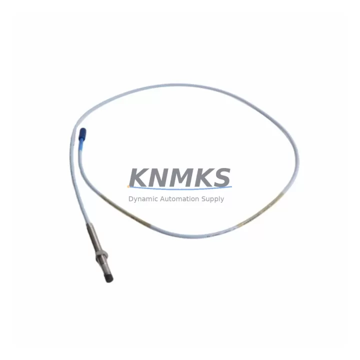
The Bently Nevada 330104-01-17-05-01-05 is an 8mm proximity transducer from the 3300 XL Series, purpose-built for continuous vibration monitoring in rotating machinery applications. As legacy Bently Nevada 3300 Series systems approach end-of-life and spare parts become increasingly scarce, this migration-ready replacement module provides a verified drop-in upgrade path that preserves existing wiring infrastructure, signal conditioning compatibility, and monitor channel calibration — minimizing retrofit risk and unplanned downtime across turbines, compressors, pumps, and gearboxes.
When planning a retrofit from an older 3300 Series transducer to the 330104-01-17-05-01-05, engineers must verify several critical parameters before committing to a cutover. Power supply capacity at the junction box or proximitor housing should be confirmed against the transducer’s bias voltage range (typically –10 VDC to –18 VDC). Terminal wiring at the field connector must match the existing cable shield grounding scheme to avoid ground loop interference on the vibration signal. The proximitor extension cable — commonly the 330130 or 330180 series — must be length-matched to maintain the system’s calibrated gap voltage curve, since cable length directly affects the overall sensitivity of the eddy-current measurement chain.
Backplane interface compatibility is equally important when the transducer feeds into a 3500 Series rack-based monitoring system. The 3500/40M or 3500/42M monitor modules must be configured for the correct transducer type and sensitivity (200 mV/mil or 7.87 V/mm) to ensure alarm setpoints remain valid after the swap. If the plant’s DCS or safety system reads 4–20 mA outputs from a 3500 Series I/O module, the scaling and zero-span calibration should be re-verified post-installation. For facilities running older 3300 Series monitors rather than the 3500 rack, the 330104-01-17-05-01-05 is backward-compatible with the 3300/16 and 3300/20 monitor cards, provided the gap voltage is re-zeroed during commissioning.
Module addressing and channel mapping in the host PLC or DCS should be documented before removal of the legacy transducer. In Bently Nevada System 1 or System 1 Evolution software environments, the transducer’s channel tag, engineering unit scaling, and alarm group assignments must be preserved or migrated to avoid false trips during the first run-up after replacement. HMI faceplate displays tied to vibration trend historians should be validated against the new transducer’s output to confirm that waveform and spectrum data continuity is maintained across the cutover boundary.
Installation space confirmation is straightforward for most applications: the 330104-01-17-05-01-05 uses a standard M8 threaded body with a 5/16–24 UNF thread form, compatible with existing bracket mounts and armored cable conduit entries used throughout the 3300 XL product family. Firmware version compatibility is not a concern at the transducer level, but the connected proximitor — such as the 330180-51-05 or 330180-90-00 — should be inspected for housing condition and connector integrity before reuse in the upgraded assembly.
Pre-shipment functional testing of each 330104-01-17-05-01-05 unit includes gap voltage linearity verification, sensitivity confirmation at the rated 200 mV/mil output, and insulation resistance check on the coaxial cable assembly. Units are shipped with a calibration record and are covered by a support terms confirmed by quotation against manufacturing defects. In-stock inventory allows same-week dispatch for urgent maintenance windows, supporting shutdown planning for facilities that cannot tolerate extended lead times on critical rotating machinery spares.
Migration Compatibility Table
| Parameter | Legacy 3300 Series | 330104-01-17-05-01-05 (3300 XL) | Notes |
|---|---|---|---|
| Transducer Body Thread | M8 / 5/16–24 UNF | M8 / 5/16–24 UNF | Direct bracket reuse |
| Sensitivity | 200 mV/mil (7.87 V/mm) | 200 mV/mil (7.87 V/mm) | No rescaling required |
| Bias Voltage Range | –10 to –18 VDC | –10 to –18 VDC | Verify power supply headroom |
| Cable Compatibility | 330130 / 330180 Series | 330130 / 330180 Series | Length-match required |
| Monitor Compatibility | 3300/16, 3300/20 | 3300/16, 3300/20, 3500/40M, 3500/42M | Re-zero gap voltage post-install |
| Communication Protocol | Analog (4–20 mA via monitor) | Analog (4–20 mA via monitor) | DCS scaling re-verification needed |
| Installation Space | Standard 3300 XL bracket | Standard 3300 XL bracket | No mechanical modification |
| Firmware Dependency | None (passive transducer) | None (passive transducer) | Proximitor firmware check recommended |
| Support terms | — | 12 Months | Covers manufacturing defects |
Retrofit Planning for Existing Automation Systems
A successful retrofit of the 330104-01-17-05-01-05 into an operating plant requires a structured bill-of-materials review that goes beyond the transducer itself. The proximitor extension cable — typically a 330180-51-05 or 330180-90-00 — must be inspected for jacket integrity and connector pin condition, as degraded cables are a leading cause of erratic gap voltage readings after an otherwise correct transducer swap. If the proximitor housing itself shows signs of moisture ingress or connector corrosion, replacing it alongside the transducer with a new 330180 Series proximitor eliminates a common callback risk.
At the monitor rack level, facilities running a 3500 Series chassis should confirm that the 3500/40M proximitor I/O module’s channel configuration matches the 3300 XL transducer type. If the plant is simultaneously upgrading from a standalone 3300/20 monitor to a 3500 rack-based system, the I/O wiring from the junction box to the rack’s terminal board must be re-routed and labeled according to the new channel map. Power distribution within the control cabinet should be reviewed to ensure the 24 VDC or 28 VDC rail supplying the proximitor circuit has sufficient current margin after adding any new monitor cards.
For facilities that also operate Bently Nevada 3500/22M transient data interface modules or 3500/32 4-channel relay modules, the alarm relay wiring and setpoint configuration must be re-validated after the transducer replacement to confirm that overall vibration and gap alarms remain correctly mapped to the plant’s safety interlock system. Signal isolators installed between the monitor output and the DCS analog input card should be checked for input impedance compatibility with the 4–20 mA signal from the 3500 monitor, particularly if the isolator was originally sized for a different monitor generation.
Programming cable access to the 3500 rack via the 3500/92 communication gateway or a direct RS-232 connection to the rack’s front panel allows engineers to perform a live channel check and confirm that vibration amplitude readings are within expected baseline range before returning the machine to service. This step is especially important when the replacement transducer is installed on a machine that feeds into a System 1 Evolution trending database, where a gap in historical data or a sudden baseline shift can trigger unnecessary maintenance investigations.
Downtime Control During System Migration
Minimizing production impact during a proximity transducer replacement begins with pre-staging all replacement components — including the 330104-01-17-05-01-05 transducer, extension cable, and any required bracket hardware — at the work site before the maintenance window opens. A pre-written commissioning checklist covering gap voltage target (typically –10.0 VDC ±0.5 VDC at the design air gap), sensitivity verification, and alarm bypass procedure allows the field team to execute the swap in a single shift without waiting for engineering support.
Where the plant’s safety system permits, placing the affected monitor channel in bypass mode before disconnecting the legacy transducer prevents a spurious vibration trip from propagating to the turbine or compressor shutdown logic. The original program logic in the host PLC or DCS should be exported and archived before any wiring changes are made, providing a recovery baseline if the new transducer’s signal requires scaling adjustments. After installation, a slow-roll run-up of the machine to minimum governor speed allows the field team to confirm that the gap voltage, 1X amplitude, and phase readings are stable before releasing the unit to full load — a process that typically adds less than 30 minutes to the overall maintenance window while substantially reducing the risk of a forced outage caused by a misconfigured channel.
For multi-machine facilities executing a fleet-wide 3300 Series to 3300 XL migration, staggering the replacements across planned maintenance intervals rather than performing a simultaneous cutover preserves at least partial production capacity throughout the upgrade campaign and allows lessons learned from the first installation to be incorporated into subsequent work packages.
Retrofit Support FAQ
Q: Is the 330104-01-17-05-01-05 a direct replacement for earlier 3300 Series 8mm transducers?
A: Yes. The 330104-01-17-05-01-05 is mechanically and electrically compatible with earlier 3300 Series 8mm proximity transducers. The thread form, sensitivity, and bias voltage range are identical, allowing direct installation into existing brackets and junction boxes without modification. Gap voltage re-zeroing is required after installation.
Q: What commissioning steps are required after installation?
A: After securing the transducer at the correct air gap, verify the bias voltage at the proximitor output connector using a calibrated voltmeter. Confirm the reading falls within the monitor’s accepted gap voltage window (typically –10.0 VDC ±0.5 VDC). Enable the monitor channel, observe the 1X vibration amplitude at slow-roll speed, and compare against the pre-outage baseline. Remove the alarm bypass and confirm relay status before returning the machine to service.
Q: How do I confirm wiring compatibility with my existing junction box?
A: The 330104-01-17-05-01-05 uses the standard Bently Nevada 3-conductor coaxial wiring scheme (center conductor, shield, and drain wire) consistent with all 3300 XL Series transducers. Existing terminal block assignments for the signal, shield, and power conductors do not need to change. Verify that the cable shield is grounded at one end only (typically at the proximitor) to prevent ground loop interference.
Q: What support terms and stock availability can I expect?
A: Each unit ships with a support terms confirmed by quotation covering manufacturing defects in materials and workmanship. Pre-shipment testing includes gap voltage linearity and sensitivity verification. In-stock units are available for same-week dispatch to support planned and emergency maintenance windows. Contact admin@knmks.com or +86 18359268345 for current stock levels and lead time confirmation.
© 2026 KNMKS. All rights reserved.
Original Source: https://knmks.com
Contact: admin@knmks.com | +86 18359268345
Product Identification
- Brand / Ecosystem
-
Bently Nevada
Bently Nevada - Model / Series
-
330104-01-17-05-01-05
Bently Nevada 3300 XL / 3301 Series - Product Family
- Sensors
- Availability Status
- Available on request after model and quantity confirmation
- Inquiry Type
- B2B RFQ, replacement inquiry and project spare-part request
- Pre-Quote Check
- Exact SKU, brand, series, quantity, nameplate photos and destination country are checked before quotation
System Path
Where this product fits in the KNMKS automation structure.
Specification & Inquiry Focus
- Sensor range
- Photoelectric, proximity and process sensors
- Common needs
- Output type, distance and connector
- Project support
- Machine detection and replacement inquiry
Buyer Confirmation
Information KNMKS checks before replying.
- Exact model
- 330104-01-17-05-01-05
- Brand / ecosystem
- Bently Nevada
- Product family
- Sensors
- Application note
- Replacement, maintenance, project build or spare-part list
- Useful photos
- Nameplate, installed unit, cabinet layout or connector side
- Delivery details
- Quantity, destination country and target schedule
Document Support
Files and notes can be confirmed during quotation.
- Product photos or nameplate confirmation when available
- Packing and delivery notes before quotation confirmation
- Support scope and delivery terms confirmed per inquiry
- Export document coordination for qualified B2B requests
Inquiry Support
- NPN/PNP, analog and digital output checking
- Connector and cable compatibility review
- Fast inquiry support for maintenance teams
What to Send Us
- Brand and exact model number: Bently Nevada 330104-01-17-05-01-05
- Quantity and required delivery time
- Application, replacement requirement or nameplate photo
- Destination country and shipping preference
RFQ Preparation
This is a product inquiry page built for RFQ communication.
Fast Model Check
Send this model to KNMKS for confirmation.
Include quantity, destination country and photos if this is a maintenance replacement. The inquiry will be saved with a reference number after submission.
Brand & Compatibility Note
KNMKS displays automation product information for well-known industrial brand ecosystems and compatible replacement references. Brand names are used for product identification and compatibility reference only; final availability and commercial terms are confirmed per quotation.
 Manufacturing
 Machine Tools
 Packaging
 Energy & Power



 PLCs & Controllers
 HMI & Displays
 Servo Systems
 Variable Frequency Drives