
Overview
Bently Nevada 330104-00-24-10-01-CN Migration-Ready Proximity Probe for Legacy Control Systems
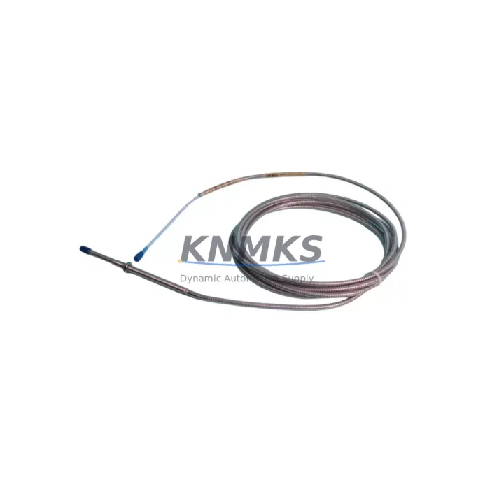
The Bently Nevada 330104-00-24-10-01-CN is an 8mm proximity probe engineered for the 3300 XL Series vibration monitoring platform. As aging distributed control systems and machinery protection systems approach end-of-life, this probe serves as a critical migration-ready replacement component for facilities undertaking legacy control system modernization. Whether you are replacing a discontinued 330104 series probe, upgrading a rotating machinery protection cabinet, or restoring a dormant monitoring loop, the 330104-00-24-10-01-CN delivers verified electrical and mechanical compatibility with existing 3300 XL field wiring, extension cables, and Proximitor® sensor assemblies.
Before initiating a swap-out, engineers should confirm the following parameters against the existing installation: probe tip diameter (8mm), cable length (24 inches / 610 mm), connector type (CN — standard coaxial), gap voltage range (−10 VDC nominal at 50 mil gap), and sensitivity (200 mV/mil). These specifications must align with the paired Proximitor® sensor — typically a 330180 or 330185 series unit — to maintain calibrated output to the 3500 Series rack or legacy 3300 Series monitor. Mismatched sensitivity between probe and Proximitor® will cause erroneous vibration readings and may trigger nuisance trips during commissioning.
For installations migrating from older 7200 Series or 3300 Series monitors to the current 3500 Series machinery protection system, the 330104-00-24-10-01-CN integrates directly without re-cabling, provided the extension cable — such as a 330130 series armored extension — remains in serviceable condition. Field technicians should inspect the extension cable for jacket integrity, connector corrosion, and continuity before reuse. If the extension cable is being replaced simultaneously, the 330130-080-00-00 (8-meter) is a common pairing for this probe length.
Migration Compatibility Table
| Parameter | 330104-00-24-10-01-CN Specification | Migration Notes |
|---|---|---|
| Probe Tip Diameter | 8 mm | Confirm existing bore/bracket accepts 8mm body; no machining required for standard 3300 XL installations |
| Cable Length | 24 in (610 mm) | Verify routing distance to junction box; pair with 330130 extension cable if additional reach is needed |
| Connector Type | CN (Coaxial) | Mates directly with 330130 series extension cables; no adapter required |
| Sensitivity | 200 mV/mil | Must match paired Proximitor® sensor (330180 / 330185 series); verify before powering system |
| Supply Voltage | −24 VDC (from Proximitor®) | Confirm Proximitor® output voltage; 3500 rack power supply must deliver stable −24 VDC to field loop |
| Compatible Monitors | 3300 XL, 3500 Series | Drop-in replacement for 3300 XL; 3500 Series requires channel configuration in System 1 or rack keypad |
| Communication Protocol | Analog (4–20 mA / voltage output via monitor) | DCS integration via 3500 monitor analog output; confirm I/O card wiring at DCS marshalling cabinet |
| Installation Space | Standard 3300 XL probe bracket | No bracket modification required; confirm probe body clearance to shaft surface (50 mil nominal gap) |
| Firmware Compatibility | N/A (passive transducer) | No firmware update required; 3500 monitor firmware version should be ≥ 3.x for full diagnostic support |
| Support terms | 12 Months | Covers manufacturing defects; includes pre-shipment functional test and calibration verification |
Retrofit Planning for Existing Automation Systems
A successful retrofit of the 330104-00-24-10-01-CN into an operating plant begins well before the maintenance window opens. The first step is a full loop audit: trace the signal path from the probe tip through the 330130 series extension cable, into the Proximitor® sensor enclosure, and back to the 3500/20 rack input card. Document terminal numbers at each junction, confirm shield grounding practice (single-point at the monitor end), and photograph existing wiring before disconnection. This documentation becomes the baseline for post-installation verification.
Power supply capacity is a frequent oversight in probe replacement projects. The 3500 rack’s internal power supply — or an external −24 VDC supply feeding a legacy 3300 monitor — must be confirmed to have sufficient current headroom for the new probe loop. A single 330104 probe draws minimal current, but in multi-channel cabinets where several probes are being replaced simultaneously, cumulative load should be recalculated against the supply’s rated output.
When the control cabinet also houses a 3500/22M transient data interface or a 3500/42M proximitor monitor card, technicians should verify that the channel configuration stored in the rack’s non-volatile memory still reflects the correct probe type, gap range, and alert/danger setpoints after the replacement. If the plant uses Bently Nevada System 1 software for online machinery diagnostics, the channel configuration should be exported before the outage and re-validated after probe installation to confirm that trend data continuity is maintained.
For facilities running a mixed-generation control architecture — where a legacy Allen-Bradley PLC or Siemens S7 series controller receives discrete trip signals from the 3500 rack — the I/O wiring at the PLC input card should be verified for correct voltage levels and contact ratings. The 3500 rack’s relay output module delivers dry contact closures; confirm that the PLC input card’s 24 VDC sourcing or sinking configuration matches the existing wiring scheme before re-energizing the loop.
HMI screens tied to the machinery protection system should also be reviewed. If the plant uses a Wonderware or FactoryTalk View HMI, tag addresses linked to the 3500 monitor’s Modbus or Ethernet/IP output should be confirmed unchanged after the probe swap. In most cases, a passive transducer replacement like the 330104-00-24-10-01-CN does not alter the monitor’s communication output, but a full HMI data validation pass during commissioning is recommended practice to catch any configuration drift introduced during the outage.
Downtime Control During System Migration
Minimizing unplanned downtime during a proximity probe replacement requires a structured pre-outage preparation protocol. Before the maintenance window, the replacement 330104-00-24-10-01-CN should be bench-tested using a calibrated gap simulator to confirm output voltage at the nominal 50 mil gap. This pre-shipment functional test — included with every unit supplied by KNMKS — reduces the risk of discovering a defective component after the machine is already offline.
To protect the original program logic in the connected 3500 rack or legacy 3300 monitor, all setpoint configurations, channel assignments, and relay logic should be exported and saved to a secure backup location before the outage begins. If the rack uses a System 1 configuration file, a timestamped backup should be created and stored off the rack. This ensures that in the event of an unexpected rack reset during the maintenance window, the configuration can be restored without manual re-entry of setpoints — a process that can add hours to an unplanned outage.
Field control continuity during the swap can be maintained by placing the affected monitor channel in bypass mode before disconnecting the probe. Most 3500 series monitors support channel bypass via the front-panel keypad or System 1 software, which suppresses trip outputs on that channel while the probe is disconnected. This prevents a nuisance machine trip during the physical probe replacement and gap-setting procedure. Once the new 330104-00-24-10-01-CN is installed and gapped, the channel should be returned to normal monitoring mode and the output voltage verified before the bypass is removed.
Post-installation commissioning should include a full gap voltage measurement at the Proximitor® output, a signal path continuity check from probe to monitor input card, and a review of the monitor’s OK relay status. If the 3500 rack is connected to a plant DCS via the 3500/92 communication gateway, a data integrity check on the Modbus register map should be performed to confirm that vibration, gap, and speed values are being correctly transmitted to the DCS historian before the machine is returned to service.
Retrofit Support FAQ
Q1: Is the 330104-00-24-10-01-CN a direct drop-in replacement for the original 330104-00-24-10-01-CN installed in my 3300 XL system?
Yes. The replacement unit is manufactured to the same dimensional and electrical specifications as the original Bently Nevada 330104-00-24-10-01-CN. It is compatible with existing 330130 series extension cables, 330180/330185 Proximitor® sensors, and 3300 XL or 3500 Series monitor inputs without modification.
Q2: What pre-shipment testing is performed on each unit?
Every 330104-00-24-10-01-CN supplied by KNMKS undergoes a functional output voltage test at the nominal 50 mil gap, a cable continuity check, and a connector integrity inspection before shipment. A test report is available upon request. All units are covered by a support terms confirmed by quotation against manufacturing defects from the date of shipment.
Q3: Can this probe be used with a 3500 Series rack if we are migrating from a legacy 3300 monitor?
Yes. The 330104-00-24-10-01-CN is fully compatible with the 3500 Series machinery protection system. When migrating from a 3300 monitor, the channel configuration in the 3500 rack must be set to match the probe’s 200 mV/mil sensitivity and the expected gap voltage range. No hardware modification to the probe or extension cable is required.
Q4: What is your typical lead time and do you maintain stock?
KNMKS maintains inventory of the 330104-00-24-10-01-CN to support urgent maintenance and planned retrofit projects. Standard lead time for in-stock units is 3–7 business days for international shipments. For large-quantity orders or scheduled plant turnarounds, contact our sales team to confirm availability and arrange priority dispatch.
© 2026 KNMKS. All rights reserved.
Original Source: https://knmks.com
Contact: admin@knmks.com | +86 18359268345
Product Identification
- Brand / Ecosystem
-
Bently Nevada
Bently Nevada - Model / Series
-
330104-00-24-10-01-CN
Bently Nevada 3300 XL / 3301 Series - Product Family
- Sensors
- Availability Status
- Available on request after model and quantity confirmation
- Inquiry Type
- B2B RFQ, replacement inquiry and project spare-part request
- Pre-Quote Check
- Exact SKU, brand, series, quantity, nameplate photos and destination country are checked before quotation
System Path
Where this product fits in the KNMKS automation structure.
Specification & Inquiry Focus
- Sensor range
- Photoelectric, proximity and process sensors
- Common needs
- Output type, distance and connector
- Project support
- Machine detection and replacement inquiry
Buyer Confirmation
Information KNMKS checks before replying.
- Exact model
- 330104-00-24-10-01-CN
- Brand / ecosystem
- Bently Nevada
- Product family
- Sensors
- Application note
- Replacement, maintenance, project build or spare-part list
- Useful photos
- Nameplate, installed unit, cabinet layout or connector side
- Delivery details
- Quantity, destination country and target schedule
Document Support
Files and notes can be confirmed during quotation.
- Product photos or nameplate confirmation when available
- Packing and delivery notes before quotation confirmation
- Support scope and delivery terms confirmed per inquiry
- Export document coordination for qualified B2B requests
Inquiry Support
- NPN/PNP, analog and digital output checking
- Connector and cable compatibility review
- Fast inquiry support for maintenance teams
What to Send Us
- Brand and exact model number: Bently Nevada 330104-00-24-10-01-CN
- Quantity and required delivery time
- Application, replacement requirement or nameplate photo
- Destination country and shipping preference
RFQ Preparation
This is a product inquiry page built for RFQ communication.
Fast Model Check
Send this model to KNMKS for confirmation.
Include quantity, destination country and photos if this is a maintenance replacement. The inquiry will be saved with a reference number after submission.
Brand & Compatibility Note
KNMKS displays automation product information for well-known industrial brand ecosystems and compatible replacement references. Brand names are used for product identification and compatibility reference only; final availability and commercial terms are confirmed per quotation.
 Manufacturing
 Machine Tools
 Packaging
 Energy & Power



 PLCs & Controllers
 HMI & Displays
 Servo Systems
 Variable Frequency Drives