
Overview
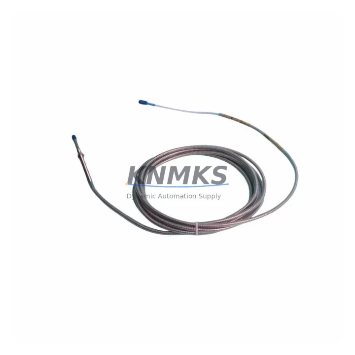
Bently Nevada 330104-00-23-10-02-CN Migration-Ready Proximity Transducer for Legacy Control Systems
The Bently Nevada 330104-00-23-10-02-CN is an 8mm proximity transducer engineered for seamless integration into legacy vibration monitoring and machinery protection systems built on the 3300 XL platform. As original equipment manufacturers phase out older transducer assemblies and discontinue support for first-generation 3300 Series components, plant engineers and reliability teams increasingly rely on migration-ready replacements that preserve existing wiring infrastructure, maintain signal chain integrity, and eliminate the need for full system overhauls. The 330104-00-23-10-02-CN is purpose-built for exactly this scenario — delivering a verified drop-in replacement path that minimizes downtime, protects program logic, and extends the operational life of installed control architectures.
Whether you are replacing a failed transducer on a critical rotating asset, upgrading a legacy monitoring loop ahead of a planned outage, or consolidating spare parts inventory across multiple plant sites, the 330104-00-23-10-02-CN provides the dimensional compatibility, output signal specification, and connector interface required to restore full system functionality without modifying existing cable runs or reconfiguring monitor channel assignments.
Migration Compatibility Table
| Parameter | 330104-00-23-10-02-CN | Notes / Retrofit Guidance |
|---|---|---|
| Probe Diameter | 8 mm | Direct fit for standard 3300 XL mounting bosses; no re-boring required |
| Cable Length | 1.0 m integral cable | Verify extension cable length matches existing field run; use 330130 series extension if needed |
| Output Signal | −200 mV/mil (−7.87 V/mm) | Compatible with 3300 XL monitor input sensitivity; no channel rescaling required |
| Power Supply | −24 VDC (via driver/oscillator) | Confirm driver output voltage at terminal block before installation; typical range −18 to −26 VDC |
| Connector Interface | Standard BNC / integral | Matches legacy field wiring; inspect connector pins for corrosion before mating |
| Mounting Thread | M10 × 1.0 | Confirm thread condition in bearing housing; re-tap if necessary before installation |
| Communication Compatibility | Analog (passive transducer) | No protocol migration required; signal feeds directly into 3300 XL monitor or compatible Rack Interface Module |
| Replacement Recommendation | Direct replacement for 330104 series | Verify gap voltage at commissioning; target −10.0 VDC ± 0.5 VDC at nominal air gap |
| Commissioning Focus | Gap voltage, sensitivity, alarm setpoints | Re-verify vibration alarm and danger setpoints in monitor after replacement |
| Support terms | support terms confirmed by quotation | Covers manufacturing defects; includes pre-shipment functional test documentation |
Retrofit Planning for Existing Automation Systems
Successful integration of the 330104-00-23-10-02-CN into an existing machinery protection architecture requires a structured pre-installation review. Begin by auditing the installed driver/oscillator — typically a 330180 series proximitor or equivalent — to confirm output voltage stability and cable impedance match. The proximitor converts the transducer’s eddy-current signal into a usable DC voltage; a degraded driver will produce erratic gap readings even with a new probe installed, so replacement of both components should be evaluated together when the system has been in service for more than ten years.
Next, inspect the extension cable assembly connecting the probe to the proximitor. In many legacy installations, the 330130 series extension cable has been routed through conduit shared with power conductors, introducing noise that can mask genuine vibration events or trigger nuisance alarms. During the retrofit window, re-routing or replacing the extension cable eliminates a common source of signal degradation that is frequently misattributed to transducer failure.
At the monitor level, confirm that the 3300 XL monitor module — whether a standard vibration monitor, a thrust position monitor, or a differential expansion module — is configured for the correct transducer sensitivity and gap range. If the control cabinet also houses a 3300/16 Rack Interface Module or a 3500 series monitor as part of a parallel upgrade path, verify that channel addressing and rack slot assignments are documented before any hardware is disturbed. Mislabeled terminal blocks and undocumented jumper settings are among the most common causes of extended commissioning time during legacy system retrofits.
For plants operating integrated control and safety systems, the transducer replacement may interact with HMI display configurations tied to specific channel tags. Coordinate with the DCS or SCADA team to confirm that historian tags, alarm annunciation screens, and trend displays reference the correct physical channel after the replacement is complete. In facilities where the 3300 XL system feeds a Bently Nevada System 1 condition monitoring platform, re-synchronize the channel configuration in System 1 software following the hardware change to ensure continuous data integrity.
Installation space confirmation is straightforward for most 8mm probe applications, but in compact bearing housings or tight machine train arrangements, verify probe tip clearance and cable bend radius before finalizing the mounting position. Allow adequate service loop in the integral cable to permit future probe removal without stressing the connector junction.
Downtime Control During System Migration
Minimizing production impact during a transducer replacement begins with pre-staging all replacement components and tools before the maintenance window opens. For the 330104-00-23-10-02-CN, this means having the replacement probe, a calibrated gap-setting tool, a digital multimeter for gap voltage verification, and the original channel configuration printout from the 3300 XL monitor ready at the work site before the machine is taken offline.
Where process conditions permit, perform a pre-outage baseline measurement of gap voltage, vibration amplitude, and DC gap on the existing transducer. This baseline serves as the acceptance reference for the replacement unit and allows the commissioning technician to confirm that the new probe is performing within the expected envelope before the machine is returned to service. Document the as-found and as-left gap voltage readings in the maintenance record to support future reliability analysis.
To protect existing program logic, avoid modifying monitor configuration parameters during the transducer swap unless a documented engineering change order requires it. Alarm setpoints, danger setpoints, and time-delay settings should be recorded before the monitor is placed in bypass mode and restored exactly after the new transducer is installed and gap-verified. In systems where the 3300 XL monitor is networked to a plant DCS via a 4–20 mA output or a Modbus link, confirm that the communication link is re-established and that the DCS is receiving valid process values before releasing the bypass.
For critical machinery where continuous monitoring is required, consider a temporary portable vibration monitoring solution to maintain surveillance during the replacement window. This approach is particularly valuable on compressors, turbines, and pumps where API 670 compliance requires uninterrupted protection coverage. Pre-shipment functional testing of the 330104-00-23-10-02-CN, combined with in-stock availability and same-day dispatch capability, supports tight maintenance scheduling and reduces the risk of extended outages caused by parts procurement delays.
Retrofit Support FAQ
Q: Is the 330104-00-23-10-02-CN a direct replacement for the original 330104-00-23-10-02 without the CN suffix?
A: Yes. The CN designation indicates a configuration variant optimized for the standard 3300 XL system architecture. The probe dimensions, output sensitivity, and connector interface are identical to the base 330104-00-23-10-02. No wiring modifications or monitor reconfiguration are required for a direct swap.
Q: What gap voltage should I expect after installing the replacement transducer?
A: At the nominal air gap specified for your application (typically 1.0 mm for most rotating machinery), the gap voltage should read approximately −10.0 VDC ± 0.5 VDC when measured at the proximitor output terminals. Deviations outside this range indicate a gap adjustment is needed or that the driver/oscillator requires inspection.
Q: Has this unit been tested before shipment?
A: Yes. Every 330104-00-23-10-02-CN unit undergoes pre-shipment functional testing covering output sensitivity, gap linearity, and connector integrity. Test documentation is available upon request. All units are supplied with a support terms confirmed by quotation covering manufacturing defects from the date of shipment.
Q: What is your typical lead time and do you maintain stock?
A: We maintain in-stock inventory of the 330104-00-23-10-02-CN to support urgent replacement requirements. Standard orders are dispatched within 1–2 business days. For large-quantity orders or multi-site procurement programs, contact our sales team to discuss dedicated stock allocation and scheduled delivery arrangements.
© 2026 KNMKS. All rights reserved.
Original Source: https://knmks.com
Contact: admin@knmks.com | +86 18359268345
Product Identification
- Brand / Ecosystem
-
Bently Nevada
Bently Nevada - Model / Series
-
330104-00-23-10-02-CN
Bently Nevada 3300 XL / 3301 Series - Product Family
- Sensors
- Availability Status
- Available on request after model and quantity confirmation
- Inquiry Type
- B2B RFQ, replacement inquiry and project spare-part request
- Pre-Quote Check
- Exact SKU, brand, series, quantity, nameplate photos and destination country are checked before quotation
System Path
Where this product fits in the KNMKS automation structure.
Specification & Inquiry Focus
- Sensor range
- Photoelectric, proximity and process sensors
- Common needs
- Output type, distance and connector
- Project support
- Machine detection and replacement inquiry
Buyer Confirmation
Information KNMKS checks before replying.
- Exact model
- 330104-00-23-10-02-CN
- Brand / ecosystem
- Bently Nevada
- Product family
- Sensors
- Application note
- Replacement, maintenance, project build or spare-part list
- Useful photos
- Nameplate, installed unit, cabinet layout or connector side
- Delivery details
- Quantity, destination country and target schedule
Document Support
Files and notes can be confirmed during quotation.
- Product photos or nameplate confirmation when available
- Packing and delivery notes before quotation confirmation
- Support scope and delivery terms confirmed per inquiry
- Export document coordination for qualified B2B requests
Inquiry Support
- NPN/PNP, analog and digital output checking
- Connector and cable compatibility review
- Fast inquiry support for maintenance teams
What to Send Us
- Brand and exact model number: Bently Nevada 330104-00-23-10-02-CN
- Quantity and required delivery time
- Application, replacement requirement or nameplate photo
- Destination country and shipping preference
RFQ Preparation
This is a product inquiry page built for RFQ communication.
Fast Model Check
Send this model to KNMKS for confirmation.
Include quantity, destination country and photos if this is a maintenance replacement. The inquiry will be saved with a reference number after submission.
Brand & Compatibility Note
KNMKS displays automation product information for well-known industrial brand ecosystems and compatible replacement references. Brand names are used for product identification and compatibility reference only; final availability and commercial terms are confirmed per quotation.
 Manufacturing
 Machine Tools
 Packaging
 Energy & Power



 PLCs & Controllers
 HMI & Displays
 Servo Systems
 Variable Frequency Drives