
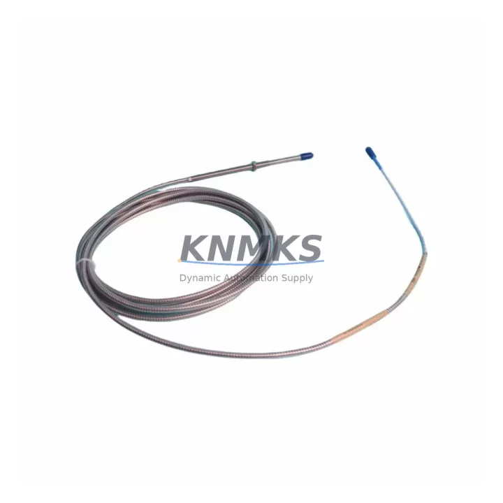
Overview
Bently Nevada 330104-00-23-10-02-00 Migration-Ready Proximity Transducer for Legacy 3300 XL Control Systems
The Bently Nevada 330104-00-23-10-02-00 is an 8mm eddy-current proximity transducer engineered for the 3300 XL Series machinery protection platform. As legacy Bently Nevada 3300 Series installations approach end-of-service milestones, plant engineers and reliability teams increasingly rely on verified drop-in replacements to extend operational life, avoid unplanned shutdowns, and defer full system overhauls. This unit delivers the same 200 mV/mil (7.87 V/mm) sensitivity, -18 VDC nominal bias voltage, and 5–10,000 Hz frequency response as the original factory specification, making it a direct functional substitute for aging or discontinued transducer assemblies across rotating machinery applications including compressors, turbines, pumps, and gearboxes.
When planning a retrofit around the 330104-00-23-10-02-00, engineers must confirm several critical parameters before committing to a swap. Power supply capacity at the junction box or monitor rack should be verified against the transducer’s -24 VDC supply requirement. Terminal wiring at the field junction box must match the existing three-wire coaxial cable configuration (drive, return, and shield), and cable length must remain within the qualified extension cable range to preserve calibration accuracy. The 330104-00-23-10-02-00 is designed for use with the Bently Nevada 3300 XL 8mm Extension Cable and the 3300 XL Proximitor Sensor, and the complete loop must be recalibrated if any cable segment is replaced. Backplane slot addressing within the 3500 Series rack or legacy 3300 rack should be confirmed against the existing I/O map to avoid channel conflicts during hot-swap procedures.
Program compatibility is a key concern during any transducer migration. If the host monitor is a Bently Nevada 3500/42M Proximitor/Seismic Monitor or a 3500/40M Proximitor Monitor, the existing configuration database should be exported and backed up before the swap. Alert and danger setpoints, gap voltage windows, and OK relay logic stored in the monitor must be re-verified post-installation. HMI screens connected via Modbus RTU or the System 1 Condition Monitoring Software should be checked to confirm that tag names, engineering unit scaling, and alarm display logic remain consistent after the transducer replacement. Where the plant uses a 3500/22M Transient Data Interface for waveform capture, the sampling configuration should be reviewed to ensure the new transducer’s frequency response aligns with the existing acquisition parameters.
Installation space confirmation is essential in congested machinery trains. The 330104-00-23-10-02-00 uses a standard M10 x 1 thread with a 5/16-24 UNF adapter option, and the probe body length of 23 mm must be matched against the existing bracket and target gap. Firmware version compatibility between the Proximitor Sensor and the 3500 monitor rack should be confirmed with the Bently Nevada firmware compatibility matrix, particularly for installations that have undergone partial rack upgrades mixing 3300 and 3500 generation hardware. Field commissioning should include a static gap check at -10.0 VDC ± 0.5 VDC, a dynamic signal verification using a calibration spindle or known-good reference shaft, and a final OK relay confirmation before returning the machine to service.
All units are pre-tested prior to shipment, with functional verification against Bently Nevada factory acceptance criteria. In-stock inventory supports rapid dispatch to minimize planned maintenance windows and emergency replacement lead times. Each 330104-00-23-10-02-00 is covered by a support terms confirmed by quotation against manufacturing defects, with traceability documentation available upon request for quality-critical installations.
Migration Compatibility Table
| Parameter | Specification / Recommendation |
|---|---|
| SKU / Part Number | 330104-00-23-10-02-00 |
| Series | Bently Nevada 3300 XL |
| Probe Diameter | 8 mm |
| Thread | M10 x 1 (5/16-24 UNF adapter available) |
| Sensitivity | 200 mV/mil (7.87 V/mm) |
| Bias Voltage | -18 VDC nominal |
| Supply Voltage | -24 VDC |
| Frequency Response | 5–10,000 Hz |
| Cable Interface | 3300 XL 8mm Extension Cable (coaxial, 3-wire) |
| Compatible Monitors | 3500/40M, 3500/42M, 3300 Series Monitors |
| Communication Protocol | Modbus RTU / System 1 Software compatible |
| Installation Thread Depth | Confirm bracket clearance for 23 mm probe body |
| Firmware Compatibility | Verify 3500 rack firmware vs. Proximitor generation |
| Commissioning Check | Static gap: -10.0 VDC ± 0.5 VDC; dynamic signal verification required |
| Replacement Scope | Direct drop-in for discontinued 330104 series variants |
| Support terms | support terms confirmed by quotation — manufacturing defects covered |
Retrofit Planning for Existing Automation Systems
A successful retrofit centered on the 330104-00-23-10-02-00 typically involves coordinating several interdependent components within the same control cabinet or machinery protection rack. The Bently Nevada 3300 XL Proximitor Sensor must be confirmed as compatible with the replacement probe before installation, as mismatched Proximitor-probe combinations will produce out-of-range gap voltages and false OK relay trips. Where the existing Proximitor is also approaching end-of-life, a simultaneous replacement using a current-production 3300 XL Proximitor Sensor eliminates the risk of a secondary failure shortly after the transducer swap.
Power distribution within the 3500 Series rack should be reviewed using the 3500 Rack Configuration Software before adding or replacing transducer channels. The 3500/15 Power Supply Module provides the regulated -24 VDC rail that feeds Proximitor Sensors, and its available current budget must accommodate all active channels after the retrofit. In multi-channel installations, the 3500/20 Rack Interface Module handles communication between the rack and the host DCS or safety system, and its configuration database should be updated to reflect any channel reassignments made during the retrofit.
For plants migrating from older 3300 Series racks to the 3500 platform, the 3500/22M Transient Data Interface is frequently added during the same outage window to enable waveform-level diagnostics that were unavailable on the legacy system. I/O terminal assignments on the 3500/40M or 3500/42M monitor cards must be mapped against the existing field wiring schedule to confirm that the replacement transducer’s drive, return, and shield conductors land on the correct terminals. Where field cable runs exceed the qualified length for the 330104-00-23-10-02-00, a 3300 XL Extension Cable of the appropriate length must be sourced and installed as part of the same work order to maintain calibration traceability.
In installations where the machinery protection system interfaces with a Rockwell Automation ControlLogix or Allen-Bradley PLC via hardwired relay contacts or analog 4–20 mA outputs, the I/O module termination at the PLC chassis should be verified after the transducer swap to confirm that alert and danger relay states are correctly mapped to the PLC input card. This is particularly important in plants where the PLC program uses the OK relay state from the Bently Nevada monitor as a permissive for startup sequences or load-shedding logic.
Downtime Control During System Migration
Minimizing unplanned downtime during a proximity transducer replacement requires a structured pre-outage preparation process. Before the maintenance window opens, the existing configuration should be fully documented: export the 3500 rack configuration database, capture screenshots of all HMI alarm pages associated with the affected machine train, and record the current gap voltage, alert setpoints, and danger setpoints for each channel being replaced. This baseline documentation allows the commissioning team to restore the original logic quickly if the replacement transducer requires adjustment.
Where the plant schedule permits only a short maintenance window, pre-staging the 330104-00-23-10-02-00 with a bench gap check and a pre-verified Proximitor Sensor before the outage begins can reduce in-field commissioning time significantly. The replacement assembly should be threaded to the correct gap distance on a calibration fixture and the output voltage confirmed at -10.0 VDC ± 0.5 VDC before the unit is brought to the machine. This eliminates the most time-consuming step of field gap adjustment and allows the technician to focus on wiring verification and monitor configuration during the live outage.
Program logic protection is equally important. If the host PLC or DCS uses the Bently Nevada monitor’s relay outputs as interlocks, those interlocks should be temporarily bypassed or placed in manual override during the transducer swap to prevent spurious trips. The bypass must be formally documented in the permit-to-work system and removed immediately after the new transducer is confirmed in service. Communication links between the 3500 rack and the System 1 Condition Monitoring Software should be verified post-installation to confirm that trend data collection resumes without gaps, preserving the historical baseline for future diagnostic comparison.
Retrofit Support FAQ
Q: Is the 330104-00-23-10-02-00 a direct replacement for other 330104 series part numbers?
A: Yes. The 330104-00-23-10-02-00 is dimensionally and electrically compatible with other 330104 series variants sharing the same probe diameter, thread, and cable interface. Minor suffix differences typically reflect cable length or connector options rather than fundamental electrical changes. Confirm the probe body length and extension cable length against your existing bracket and conduit run before ordering.
Q: What commissioning steps are required after installation?
A: After mechanical installation, perform a static gap check to confirm the output voltage is within -10.0 VDC ± 0.5 VDC at the design gap distance. Verify the OK relay is energized and that the monitor channel is not in alert or danger. Reconnect the System 1 software link and confirm trend data is being received. Restore any bypassed interlocks and document the completed commissioning in the plant maintenance management system.
Q: How is wiring compatibility confirmed before installation?
A: Compare the existing field wiring schedule against the 3300 XL Extension Cable pinout. The three conductors — drive, return, and shield — must land on the correct terminals at both the junction box and the monitor card. If the existing cable is being reused, inspect the connector and cable jacket for damage and verify the cable length is within the qualified range for the 330104-00-23-10-02-00 and its paired Proximitor Sensor.
Q: What does the support terms confirmed by quotation cover, and is traceability documentation available?
A: The support terms confirmed by quotation cover manufacturing defects under normal operating conditions. Each unit is functionally tested prior to shipment. Traceability documentation including test records and country of origin certification is available upon request and can be provided with the shipment for quality-critical or safety-instrumented system installations.
© 2026 KNMKS. All rights reserved.
Original Source: https://knmks.com
Contact: admin@knmks.com | +86 18359268345
Product Identification
- Brand / Ecosystem
-
Bently Nevada
Bently Nevada - Model / Series
-
330104-00-23-10-02-00
Bently Nevada 3300 XL / 3301 Series - Product Family
- Sensors
- Availability Status
- Available on request after model and quantity confirmation
- Inquiry Type
- B2B RFQ, replacement inquiry and project spare-part request
- Pre-Quote Check
- Exact SKU, brand, series, quantity, nameplate photos and destination country are checked before quotation
System Path
Where this product fits in the KNMKS automation structure.
Specification & Inquiry Focus
- Sensor range
- Photoelectric, proximity and process sensors
- Common needs
- Output type, distance and connector
- Project support
- Machine detection and replacement inquiry
Buyer Confirmation
Information KNMKS checks before replying.
- Exact model
- 330104-00-23-10-02-00
- Brand / ecosystem
- Bently Nevada
- Product family
- Sensors
- Application note
- Replacement, maintenance, project build or spare-part list
- Useful photos
- Nameplate, installed unit, cabinet layout or connector side
- Delivery details
- Quantity, destination country and target schedule
Document Support
Files and notes can be confirmed during quotation.
- Product photos or nameplate confirmation when available
- Packing and delivery notes before quotation confirmation
- Support scope and delivery terms confirmed per inquiry
- Export document coordination for qualified B2B requests
Inquiry Support
- NPN/PNP, analog and digital output checking
- Connector and cable compatibility review
- Fast inquiry support for maintenance teams
What to Send Us
- Brand and exact model number: Bently Nevada 330104-00-23-10-02-00
- Quantity and required delivery time
- Application, replacement requirement or nameplate photo
- Destination country and shipping preference
RFQ Preparation
This is a product inquiry page built for RFQ communication.
Fast Model Check
Send this model to KNMKS for confirmation.
Include quantity, destination country and photos if this is a maintenance replacement. The inquiry will be saved with a reference number after submission.
Brand & Compatibility Note
KNMKS displays automation product information for well-known industrial brand ecosystems and compatible replacement references. Brand names are used for product identification and compatibility reference only; final availability and commercial terms are confirmed per quotation.
 Manufacturing
 Machine Tools
 Packaging
 Energy & Power



 PLCs & Controllers
 HMI & Displays
 Servo Systems
 Variable Frequency Drives