
Overview
Bently Nevada 330104-00-22-50-02-00 Migration-Ready Proximity Transducer: Legacy System Retrofit & Compatibility Upgrade
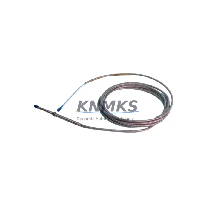
The Bently Nevada 330104-00-22-50-02-00 is an 8mm proximity transducer engineered for the 3300 XL Series continuous monitoring platform. As legacy vibration monitoring systems reach end-of-life and OEM spare parts become increasingly scarce, this migration-ready transducer provides a verified drop-in replacement path for facilities operating aging Bently Nevada 3300, 3300/16, and 3300 XL rack-based monitoring systems. Whether you are executing a planned control system modernization, responding to an unplanned equipment failure, or extending the service life of an existing machinery protection system, the 330104-00-22-50-02-00 delivers the dimensional accuracy, signal output, and connector compatibility required to restore full monitoring capability with minimal downtime.
For maintenance engineers and reliability teams managing rotating machinery — including steam turbines, gas compressors, centrifugal pumps, and large induction motors — the ability to source a functionally equivalent transducer without redesigning the monitoring loop is critical. The 330104-00-22-50-02-00 maintains the standard -24 VDC bias voltage output, 200 mV/mil (7.87 V/mm) scale factor, and 5–90 mil (0.127–2.286 mm) linear range that the 3300 XL monitor cards expect, ensuring that existing alarm and danger setpoints, Keyphasor® reference signals, and trend data continuity are preserved across the replacement event.
Migration Compatibility Table
| Parameter | 330104-00-22-50-02-00 Specification | Retrofit / Migration Notes |
|---|---|---|
| Probe Tip Diameter | 8 mm | Direct fit for existing 8mm probe bosses; no machining required |
| Cable Length | 0.5 m (500 mm) integral cable | Verify extension cable length to reach junction box; use 330130 series extension if needed |
| Thread Size | M10 × 1.0 | Confirm existing probe boss thread before installation; no adapter required for standard 3300 XL installations |
| Connector Type | Integral coaxial, mates with 330130 extension cable | Inspect existing extension cable connector for wear; replace 330130-080-00-00 extension if signal integrity is compromised |
| Scale Factor | 200 mV/mil (7.87 V/mm) | No recalibration of monitor card required; setpoints remain valid |
| Bias Voltage Output | −10.0 to −18.0 VDC (nominal −12 VDC at 50 mil gap) | Verify driver/extension system output at OK relay before returning to service |
| Compatible Monitor Cards | 3300/16, 3300/25, 3300/46, 3300/55 XL series | Confirm monitor card firmware revision supports current transducer OK limits |
| Driver / Extension System | 3300 XL 8mm System (probe + extension + driver) | Replace full proximitor system (330180 driver) if bias voltage is out of range after probe swap |
| Installation Clearance | Standard 8mm probe housing | Confirm radial clearance in bearing housing; no additional space required vs. original |
| Communication / Protocol | Analog (4–20 mA equivalent via monitor card output) | No protocol migration required; monitor card handles signal conditioning and Modbus/FOUNDATION Fieldbus output if configured |
| Support terms | 12 Months | Covers manufacturing defects; includes pre-shipment functional verification |
Retrofit Planning for Existing Automation Systems
A successful retrofit of the 330104-00-22-50-02-00 into an operating machinery protection system requires a structured pre-outage review. Begin by auditing the complete 3300 XL transducer chain: the probe itself, the 330130 series coaxial extension cable, and the 330180 series proximitor driver module. In many legacy installations, the extension cable has been routed through conduit for a decade or more, and connector corrosion or cable jacket degradation can introduce noise that masks the true condition of a newly installed probe. If the 330130-080-00-00 extension cable shows any sign of shield continuity loss, replace it concurrently with the probe to avoid a repeat outage.
The 330180 proximitor driver — typically mounted in the field junction box or directly on the 3300 XL rack — must be verified for correct output voltage before the new probe is declared in service. Use a calibrated gap tool to set the probe-to-target gap to the nominal 50 mil (1.27 mm) and confirm the driver output reads between −10.0 and −18.0 VDC. If the driver output is outside this window, the 3300 XL monitor card will assert an OK fault, and the channel will not contribute to machinery protection logic. In that scenario, replacing the 330180 driver as part of the same work order eliminates a second planned outage.
For facilities that are simultaneously upgrading from a 3300/16 rack to a System 1 Evolution or System 1 Evo software platform, the 330104-00-22-50-02-00 remains fully compatible because the transducer signal is conditioned at the monitor card level before being passed to the data acquisition layer. No changes to the transducer or extension cable are required when migrating the software platform, provided the 3300 XL hardware rack is retained. If the rack itself is being replaced with a 3500 Series rack, note that the 3500/42M Proximitor/Seismic Monitor accepts the same 8mm transducer system, making the 330104-00-22-50-02-00 a valid interim spare during a phased hardware migration.
Control cabinet space is rarely a constraint for this transducer, as the probe and integral cable terminate outside the cabinet at the machine bearing housing. However, the 330180 proximitor driver occupies a DIN-rail or panel-mount footprint in the junction box; confirm available space if adding a redundant channel. For I/O-intensive upgrades where multiple transducer channels are being added simultaneously, the 3300 XL rack’s backplane slot count should be verified against the number of 3300/16 or 3300/25 monitor cards required. Each dual-channel monitor card occupies one rack slot, and a standard 19-inch 3300 XL rack accommodates up to 14 monitor card slots plus the power supply module.
When the machinery protection system interfaces with a DCS or safety PLC via hardwired relay contacts or 4–20 mA analog outputs, verify that the relay output wiring from the 3300 XL monitor card to the DCS I/O module remains intact after the probe swap. A transducer replacement does not alter the relay logic, but a brief OK relay dropout during installation can trigger a spurious alarm in the DCS historian. Coordinate with the control room operator to suppress the affected channel in the DCS alarm management system for the duration of the installation window.
Downtime Control During System Migration
Minimizing unplanned downtime during a proximity transducer replacement begins with pre-staging all replacement components before the maintenance window opens. For the 330104-00-22-50-02-00, this means having the probe, a spare 330130 extension cable, and a 330180 proximitor driver available at the work site before the machine is taken offline. A typical probe swap on an accessible bearing housing takes 20–40 minutes; the majority of the outage time is consumed by gap setting, bias voltage verification, and OK relay confirmation — not the mechanical installation itself.
To protect the original program logic in the 3300 XL monitor card, do not remove or re-address the monitor card during a probe-only replacement. The monitor card retains all configured alarm setpoints, OK limits, and relay assignments in non-volatile memory. If the monitor card must be removed for any reason — for example, to access a rear-panel connector — document the card address and slot position before removal, as the 3300 XL rack uses slot-based addressing that must be restored exactly to maintain the correct channel-to-machine mapping in the System 1 software database.
For facilities running continuous processes where even a brief monitoring gap is unacceptable, consider installing the 330104-00-22-50-02-00 on a spare probe boss (if available) and verifying the signal before removing the original probe. This parallel installation approach allows the monitor card to be switched to the new probe channel without a monitoring gap, and the original probe can be removed at a subsequent convenient opportunity. Where a spare probe boss is not available, coordinate the replacement with the next scheduled vibration survey to align the monitoring gap with a period of known low-risk operation.
All units are functionally tested prior to shipment, including bias voltage output verification and scale factor confirmation against a calibrated target. This pre-shipment testing reduces the risk of receiving a non-conforming unit and eliminates the need for incoming inspection beyond a visual check of the connector and cable jacket. The support terms confirmed by quotation cover manufacturing defects discovered after installation, providing coverage through at least one full planned maintenance cycle for most rotating machinery applications.
Retrofit Support FAQ
Q: Is the 330104-00-22-50-02-00 a direct replacement for the original Bently Nevada part of the same SKU?
A: Yes. The 330104-00-22-50-02-00 is manufactured to the same dimensional, electrical, and performance specifications as the original Bently Nevada part. It is a drop-in replacement for any 3300 XL 8mm proximity transducer installation using the standard M10 × 1.0 probe boss. No modifications to the extension cable, proximitor driver, or monitor card are required.
Q: What commissioning steps are required after installing the replacement probe?
A: After mechanical installation, set the probe-to-target gap to 50 mil (1.27 mm) using a calibrated gap tool. Verify the 330180 proximitor driver output voltage reads between −10.0 and −18.0 VDC. Confirm the OK relay on the 3300 XL monitor card is energized and that the channel is reading a plausible vibration level (typically <1 mil pk-pk on a stopped machine). No software reconfiguration is required unless the monitor card was replaced simultaneously.
Q: Can this transducer be used with a 3500 Series rack during a phased migration?
A: Yes. The 330104-00-22-50-02-00 is compatible with the 3500/42M Proximitor/Seismic Monitor, which accepts the same 8mm transducer system. This makes it a valid spare during a phased migration from a 3300 XL rack to a 3500 Series rack, allowing you to maintain a single transducer part number across both platforms during the transition period.
Q: What is the support terms coverage and what does pre-shipment testing include?
A: Each unit carries a support terms confirmed by quotation against manufacturing defects from the date of shipment. Pre-shipment testing includes bias voltage output verification, scale factor confirmation, and visual inspection of the connector and cable jacket. Units that do not meet specification are not shipped. Support requests are processed directly; contact admin@knmks.com with the order number and a description of the observed fault.
© 2026 KNMKS. All rights reserved.
Original Source: https://knmks.com
Contact: admin@knmks.com | +86 18359268345
Product Identification
- Brand / Ecosystem
-
Bently Nevada
Bently Nevada - Model / Series
-
330104-00-22-50-02-00
Bently Nevada 3300 XL / 3301 Series - Product Family
- Sensors
- Availability Status
- Available on request after model and quantity confirmation
- Inquiry Type
- B2B RFQ, replacement inquiry and project spare-part request
- Pre-Quote Check
- Exact SKU, brand, series, quantity, nameplate photos and destination country are checked before quotation
System Path
Where this product fits in the KNMKS automation structure.
Specification & Inquiry Focus
- Sensor range
- Photoelectric, proximity and process sensors
- Common needs
- Output type, distance and connector
- Project support
- Machine detection and replacement inquiry
Buyer Confirmation
Information KNMKS checks before replying.
- Exact model
- 330104-00-22-50-02-00
- Brand / ecosystem
- Bently Nevada
- Product family
- Sensors
- Application note
- Replacement, maintenance, project build or spare-part list
- Useful photos
- Nameplate, installed unit, cabinet layout or connector side
- Delivery details
- Quantity, destination country and target schedule
Document Support
Files and notes can be confirmed during quotation.
- Product photos or nameplate confirmation when available
- Packing and delivery notes before quotation confirmation
- Support scope and delivery terms confirmed per inquiry
- Export document coordination for qualified B2B requests
Inquiry Support
- NPN/PNP, analog and digital output checking
- Connector and cable compatibility review
- Fast inquiry support for maintenance teams
What to Send Us
- Brand and exact model number: Bently Nevada 330104-00-22-50-02-00
- Quantity and required delivery time
- Application, replacement requirement or nameplate photo
- Destination country and shipping preference
RFQ Preparation
This is a product inquiry page built for RFQ communication.
Fast Model Check
Send this model to KNMKS for confirmation.
Include quantity, destination country and photos if this is a maintenance replacement. The inquiry will be saved with a reference number after submission.
Brand & Compatibility Note
KNMKS displays automation product information for well-known industrial brand ecosystems and compatible replacement references. Brand names are used for product identification and compatibility reference only; final availability and commercial terms are confirmed per quotation.
 Manufacturing
 Machine Tools
 Packaging
 Energy & Power



 PLCs & Controllers
 HMI & Displays
 Servo Systems
 Variable Frequency Drives