
Overview
Bently Nevada 330104-00-18-10-01-CN Migration-Ready Proximity Transducer for Legacy System Retrofit
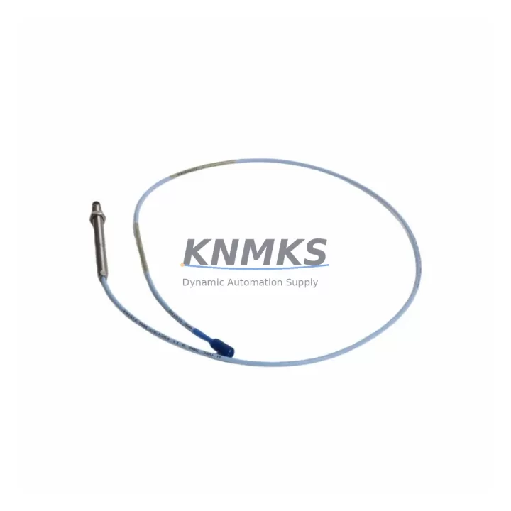
The Bently Nevada 330104-00-18-10-01-CN is a high-precision eddy-current proximity transducer engineered for the 3300 XL Series vibration monitoring platform. As aging distributed control systems and condition monitoring networks approach end-of-life, this unit serves as a verified drop-in replacement for decommissioned or obsolete transducer assemblies across rotating machinery applications including turbines, compressors, pumps, and gearboxes. Whether you are executing a full control cabinet overhaul or a targeted spare-parts replenishment to extend system life, the 330104-00-18-10-01-CN delivers the dimensional accuracy, signal output range, and connector compatibility required to restore monitoring continuity without rewriting existing PLC logic or reconfiguring HMI display screens.
Before committing to a retrofit using this transducer, engineers should verify several critical parameters on the existing installation. Power supply capacity at the junction box must support the transducer’s operating voltage range (typically –24 VDC for 3300 XL drivers), and the field cable run length must fall within the calibrated gap range for the specific driver module in use — commonly the Bently Nevada 3300 XL 8mm Extension Cable paired with a 3300 XL Proximitor Sensor. Terminal block wiring at the I/O marshalling panel should be confirmed against the original loop drawing, paying particular attention to shield grounding continuity, which directly affects signal-to-noise ratio in high-vibration environments. Backplane slot addressing and module channel assignments within the System 1 condition monitoring software must be preserved or remapped prior to energizing the replacement unit to avoid false alarm triggers or missed trip conditions.
For installations where the original transducer was mounted in a tight bearing housing or proximity probe holder with a fixed thread pitch, the 330104-00-18-10-01-CN’s 8mm probe diameter and standard metric thread ensure mechanical interchangeability without machining modifications. Armored cable routing through existing conduit pathways remains unchanged, and the standard BNC-to-MIL connector interface at the proximitor end is fully compatible with legacy junction box terminations. Firmware version alignment within the Bently Nevada 3500 Series rack — if the site has partially migrated to the newer platform — should be confirmed with the system integrator, as mixed-generation racks may require driver card parameter adjustments to accept the CN-suffix calibration curve.
Migration Compatibility Table
| Parameter | 330104-00-18-10-01-CN Specification | Retrofit Consideration |
|---|---|---|
| Probe Diameter | 8 mm | Confirm existing probe holder thread pitch (M10×1.0 standard) |
| Cable Length | 5m (integral) | Verify total system cable length against driver calibration range |
| Operating Voltage | –18 VDC to –24 VDC | Check field power supply output at junction box terminal |
| Output Sensitivity | 200 mV/mil (7.87 V/mm) | Match to existing Proximitor driver sensitivity setting |
| Target Material | AISI 4140 steel (standard) | Confirm shaft material; non-standard alloys require recalibration |
| Connector Interface | Standard BNC / MIL-C-5015 | Compatible with 3300 XL and 3500 Series junction boxes |
| Communication Protocol | Analog (4–20 mA / voltage output) | No protocol migration required; direct signal loop replacement |
| Platform Compatibility | 3300 XL Series, 3500 Series (with driver match) | Verify rack driver card firmware if using 3500 Series backplane |
| Installation Space | Standard 8mm probe body | No housing modification required for standard bearing cap mounts |
| Replacement Recommendation | Direct drop-in for 330104-00-18-10-01-CN legacy units | No PLC program changes required if channel addressing is preserved |
| Commissioning Focus | Gap voltage verification at –10 VDC ±0.5 V nominal | Perform static gap check before machine restart |
| Support terms | support terms confirmed by quotation | Covered against manufacturing defects from date of shipment |
Retrofit Planning for Existing Automation Systems
A successful retrofit begins well before the maintenance window opens. When the 330104-00-18-10-01-CN is being introduced into an existing 3300 XL monitoring loop, the first step is to audit the full signal chain from the probe tip through the Bently Nevada 3300 XL Proximitor Sensor (driver module) and into the rack I/O card. If the site is running a hybrid architecture — for example, retaining the original 3300 XL rack while adding a Bently Nevada 3500/42M Proximitor I/O Module for expanded channel capacity — the new transducer’s calibration data must be entered into both monitoring platforms to maintain alarm setpoint consistency across the HMI.
Power distribution within the control cabinet deserves particular attention. The Bently Nevada 3300 XL Power Supply feeding the proximitor rack should be load-tested before the retrofit to confirm it can support the full complement of transducers after replacement, especially if additional channels are being activated as part of the upgrade. Spare capacity of at least 20% is recommended to accommodate future I/O expansion without revisiting the power architecture.
For sites migrating from older wiring practices, the field cable shield termination at the 3300 XL Junction Box is a frequent source of post-retrofit noise complaints. Shields must be terminated at a single point — typically the junction box chassis ground — and must not be grounded at both ends. This single-point grounding rule applies equally when the replacement transducer is routed through existing conduit alongside other signal cables from Bently Nevada 330130 Velocity Transducers or thermocouple extension wiring.
If the retrofit scope includes upgrading the operator interface, HMI screen templates linked to the original transducer channel tags must be updated to reflect any new tag naming conventions before the system is returned to service. Failure to synchronize HMI tag assignments with the updated System 1 Evolution database is one of the most common causes of extended commissioning time during proximity transducer replacements. Pre-staging the HMI configuration changes in a simulation environment and validating alarm response before live cutover can reduce on-site commissioning time by 40–60%.
Where the retrofit involves replacing multiple transducers across a single machine train — for example, replacing both X-axis and Y-axis probes on a compressor bearing — it is advisable to source matched pairs of 330104-00-18-10-01-CN units from the same production batch to ensure consistent sensitivity curves. This eliminates the need for individual channel recalibration within the Bently Nevada 3500/15 Power Supply Module rack and simplifies the final acceptance test documentation.
Downtime Control During System Migration
Minimizing unplanned downtime during a proximity transducer replacement requires a structured pre-outage preparation protocol. Before the machine is taken offline, the existing gap voltage reading at each transducer channel should be recorded from the System 1 monitoring display and documented in the work order. This baseline reading serves as the acceptance criterion for the replacement unit: after installation of the 330104-00-18-10-01-CN, the static gap voltage must be re-established within ±0.5 VDC of the original value before the machine is cleared for restart.
To protect existing PLC program logic during the transition, the control system should be placed in manual override mode for the affected machine train prior to disconnecting any transducer wiring. This prevents spurious trip signals from propagating through the safety interlock chain while the signal loop is open. If the site uses a Bently Nevada 3500 Series rack with online configuration capability, the affected channel can be placed in bypass mode through the rack configuration software without interrupting monitoring on adjacent channels — a significant advantage over older 3300 XL racks that require full rack power cycling for configuration changes.
Cable continuity and insulation resistance testing of the replacement transducer assembly should be completed at the staging area before the unit is brought to the machine. A simple megohm test between the center conductor and shield at 500 VDC will confirm cable integrity and identify any shipping damage before installation. This pre-installation check, combined with a bench-top gap simulation using a calibrated target block, can reduce field commissioning time to under 30 minutes per channel for experienced technicians.
All replacement units supplied by KNMKS are pre-tested against OEM calibration specifications prior to shipment. Each 330104-00-18-10-01-CN is shipped with a calibration certificate confirming output sensitivity, linearity, and gap range compliance. The support terms confirmed by quotation cover manufacturing defects and calibration drift beyond OEM tolerance, providing assurance that the replacement unit will perform to specification throughout the initial post-retrofit operating period.
Retrofit Support FAQ
Q1: Is the 330104-00-18-10-01-CN a direct replacement for the original Bently Nevada 330104-00-18-10-01-CN, and will it work with my existing 3300 XL Proximitor driver?
Yes. The 330104-00-18-10-01-CN is a direct form-fit-function replacement for the original OEM part. It is fully compatible with the 3300 XL Proximitor driver when the total system cable length (probe cable plus extension cable) falls within the driver’s calibrated range. No driver reconfiguration is required for standard installations.
Q2: What wiring changes are needed when installing this transducer in an existing junction box?
No wiring changes are required for standard replacements. The connector interface and terminal pinout are identical to the original unit. Verify that the shield is terminated at a single point at the junction box chassis ground and that the field cable is not re-routed through areas of high electromagnetic interference. Re-torque all terminal screws to the specified value after reconnection.
Q3: How do I verify compatibility before installation, and what commissioning steps are required?
Confirm the total system cable length, target shaft material, and operating voltage at the junction box before installation. After mechanical installation, perform a static gap check by adjusting the probe position until the Proximitor output reads –10 VDC ±0.5 V with the machine at rest. Record the gap voltage and compare against the pre-removal baseline. Update the System 1 database with the new transducer serial number and calibration date before returning the machine to service.
Q4: What does the support terms confirmed by quotation cover, and how quickly can replacement stock be shipped?
The support terms confirmed by quotation cover manufacturing defects, calibration non-conformance, and premature failure under normal operating conditions from the date of shipment. KNMKS maintains ready stock of the 330104-00-18-10-01-CN and can ship within 1–3 business days for standard orders. Expedited shipping options are available for urgent maintenance situations. Contact our sales team for current inventory status and lead time confirmation.
© 2026 KNMKS. All rights reserved.
Original Source: https://knmks.com
Contact: admin@knmks.com | +86 18359268345
Product Identification
- Brand / Ecosystem
-
Bently Nevada
Bently Nevada - Model / Series
-
330104-00-18-10-01-CN
Bently Nevada 3300 XL / 3301 Series - Product Family
- Sensors
- Availability Status
- Available on request after model and quantity confirmation
- Inquiry Type
- B2B RFQ, replacement inquiry and project spare-part request
- Pre-Quote Check
- Exact SKU, brand, series, quantity, nameplate photos and destination country are checked before quotation
System Path
Where this product fits in the KNMKS automation structure.
Specification & Inquiry Focus
- Sensor range
- Photoelectric, proximity and process sensors
- Common needs
- Output type, distance and connector
- Project support
- Machine detection and replacement inquiry
Buyer Confirmation
Information KNMKS checks before replying.
- Exact model
- 330104-00-18-10-01-CN
- Brand / ecosystem
- Bently Nevada
- Product family
- Sensors
- Application note
- Replacement, maintenance, project build or spare-part list
- Useful photos
- Nameplate, installed unit, cabinet layout or connector side
- Delivery details
- Quantity, destination country and target schedule
Document Support
Files and notes can be confirmed during quotation.
- Product photos or nameplate confirmation when available
- Packing and delivery notes before quotation confirmation
- Support scope and delivery terms confirmed per inquiry
- Export document coordination for qualified B2B requests
Inquiry Support
- NPN/PNP, analog and digital output checking
- Connector and cable compatibility review
- Fast inquiry support for maintenance teams
What to Send Us
- Brand and exact model number: Bently Nevada 330104-00-18-10-01-CN
- Quantity and required delivery time
- Application, replacement requirement or nameplate photo
- Destination country and shipping preference
RFQ Preparation
This is a product inquiry page built for RFQ communication.
Fast Model Check
Send this model to KNMKS for confirmation.
Include quantity, destination country and photos if this is a maintenance replacement. The inquiry will be saved with a reference number after submission.
Brand & Compatibility Note
KNMKS displays automation product information for well-known industrial brand ecosystems and compatible replacement references. Brand names are used for product identification and compatibility reference only; final availability and commercial terms are confirmed per quotation.
 Manufacturing
 Machine Tools
 Packaging
 Energy & Power



 PLCs & Controllers
 HMI & Displays
 Servo Systems
 Variable Frequency Drives