
Overview
Bently Nevada 330104-00-17-10-01-CN Migration-Ready Proximity Transducer: Legacy System Retrofit & Compatibility Upgrade
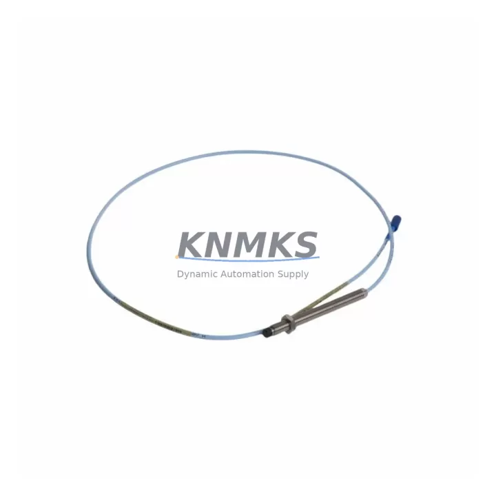
The Bently Nevada 330104-00-17-10-01-CN is a 5mm proximity transducer from the 3300 XL Series, engineered for continuous shaft vibration and position monitoring in rotating machinery. As legacy Bently Nevada 3300 Series installations approach end-of-life or face discontinued spare parts availability, this SKU serves as a verified migration-ready replacement that preserves signal integrity, wiring compatibility, and system continuity without requiring full platform overhauls.
For maintenance engineers managing aging turbine control panels, compressor monitoring racks, or DCS-integrated vibration loops, the 330104-00-17-10-01-CN provides a direct upgrade path from earlier 3300 Series transducers. Its 5mm sensing range, standard -24 VDC bias voltage output, and 200 mV/mil sensitivity align with the signal conditioning requirements of the Bently Nevada 3300/16 proximitor and 3500/42 vibration monitor modules, enabling seamless integration into existing rack-mounted monitoring systems without reprogramming the vibration alarm thresholds or reconfiguring the 3500 rack I/O assignments.
Migration Compatibility Table
| Parameter | 330104-00-17-10-01-CN (This Unit) | Legacy 3300 Series Reference | Retrofit Notes |
|---|---|---|---|
| Sensing Range | 5mm (0–2mm linear range) | 5mm standard | Direct replacement; no gap recalibration required if original gap was set correctly |
| Output Sensitivity | 200 mV/mil (7.87 V/mm) | 200 mV/mil | Compatible with 3300/16 and 3500/42 input cards |
| Bias Voltage | -10.0 VDC nominal at 1mm gap | -10.0 VDC | Verify proximitor output before connecting to monitor card |
| Cable Length | 5m (extension cable required for longer runs) | Varies by suffix | Match with 330130 extension cable for total system length compliance |
| Connector Type | MIL-C-5015 style, 2-pin | Same | No adapter required; direct plug-in replacement |
| Proximitor Compatibility | 3300/16 XL Proximitor | 3300/16, 3300/05 | Confirm proximitor firmware version supports XL transducer range |
| Monitor Card Compatibility | 3500/42, 3500/40M | 3500/42, 3500/40 | Update I/O configuration in System 1 software if switching from 3500/40 to 3500/40M |
| Installation Space | Standard 3300 XL probe body dimensions | Same form factor | No bracket modification needed for standard bearing housing mounts |
| Communication Protocol | Analog (4–20mA via proximitor) | Analog | For Modbus or PROFIBUS integration, retain existing 3500 rack gateway configuration |
| Support terms | support terms confirmed by quotation — All units are function-tested prior to shipment. Support terms covers manufacturing defects and signal output deviation beyond specification. | ||
Retrofit Planning for Existing Automation Systems
Successful integration of the 330104-00-17-10-01-CN into a legacy vibration monitoring system requires a structured pre-installation review. Begin by auditing the existing 3300/16 XL Proximitor to confirm it is operating within its specified supply voltage range of -24 VDC ±1 VDC. A degraded proximitor will produce erratic bias voltage readings even with a new transducer installed, so replacing the proximitor simultaneously — particularly if the existing unit has been in service for more than eight years — is strongly recommended to avoid repeat downtime.
Next, inspect the terminal block wiring in the control cabinet. The 330104-00-17-10-01-CN uses a standard two-conductor shielded cable configuration. Verify that the shield drain wire is grounded at one end only (typically at the proximitor end) to prevent ground loop interference, which can introduce noise into the 3500/42 vibration monitor’s gap voltage reading and trigger false alarms. If the existing cable conduit routing passes near high-voltage motor drives or variable frequency drives, consider replacing the extension cable run with a 330130 series armored extension cable to improve EMI rejection.
For systems where the 3500 rack also hosts a 3500/22M transient data interface or a 3500/32 relay module, confirm that the rack’s backplane power budget accommodates the additional transducer load. The 3500 rack power supply — typically a 3500/15 or 3500/15E — should be verified against the total module current draw before commissioning. If the rack is already near capacity, a supplemental 3500/15E power supply module may be required before adding replacement transducers across multiple measurement points.
When the plant’s DCS or safety instrumented system (SIS) receives vibration signals from the 3500 rack via a 3500/92 communication gateway, confirm that the Modbus register map or OPC-DA tag assignments remain unchanged after the transducer swap. In most cases, the 330104-00-17-10-01-CN replacement does not alter the rack’s communication output, but a full tag verification in the DCS historian — such as a System 1 Evolution or PI System data server — is recommended before returning the machine to service.
Finally, if the plant uses a Bently Nevada System 1 software platform for online machinery diagnostics, update the transducer configuration record in the System 1 database to reflect the new SKU. This ensures that the software’s alarm management, trend logging, and waveform capture functions are correctly associated with the replacement transducer’s calibration data and serial number.
Downtime Control During System Migration
Minimizing unplanned downtime during a proximity transducer replacement requires careful sequencing of the swap procedure. Where process conditions allow, perform the transducer replacement during a scheduled maintenance window rather than a forced outage. Before removing the existing transducer, document the current gap voltage reading from the 3500/42 monitor’s front-panel display or from the System 1 software trend screen. This baseline reading — typically between -9.5 VDC and -10.5 VDC for a correctly gapped 5mm transducer — serves as the acceptance criterion for the replacement unit after installation.
To protect the existing control program logic during the swap, place the affected 3500 rack channel into bypass mode using the rack’s keyswitch or through the System 1 software rack configuration interface. Bypassing the channel prevents the relay module from issuing a spurious trip signal to the turbine control system or emergency shutdown system (ESD) while the transducer is disconnected. Confirm with the control room operator that the bypass is active and logged before proceeding with the physical replacement.
After installing the 330104-00-17-10-01-CN and reconnecting the proximitor, allow a five-minute warm-up period before reading the gap voltage. Adjust the transducer axial position in the probe holder until the gap voltage matches the documented baseline within ±0.5 VDC. Once the gap is confirmed, remove the channel bypass, verify that the 3500/42 monitor displays a healthy status, and confirm that the DCS or SIS is receiving the expected vibration signal before releasing the machine for restart. This structured approach typically limits the total transducer swap time to under two hours for a single measurement point, significantly reducing the risk of extended production loss.
Retrofit Support FAQ
Q: Is the 330104-00-17-10-01-CN a direct drop-in replacement for earlier 3300 Series proximity transducers?
A: Yes, for most 3300 XL Series installations. The 330104-00-17-10-01-CN shares the same 5mm sensing range, 200 mV/mil sensitivity, and MIL-C-5015 connector as earlier 3300 Series transducers. However, confirm that your existing 3300/16 XL Proximitor is compatible with the XL transducer designation before installation, as older 3300/05 proximitors may require replacement to achieve full specification compliance.
Q: What wiring changes are required when replacing a legacy transducer with the 330104-00-17-10-01-CN?
A: In most cases, no wiring changes are required. The two-conductor shielded cable configuration and terminal block pinout are identical to the standard 3300 Series installation. Verify that the shield grounding point is maintained at the proximitor end only, and inspect the cable connector for corrosion or mechanical damage before reusing the existing cable run.
Q: How is the 330104-00-17-10-01-CN tested before shipment?
A: Every unit undergoes a full functional test prior to shipment, including bias voltage output verification, sensitivity calibration check, and connector integrity inspection. A test report is available upon request. All units are covered by a support terms confirmed by quotation against manufacturing defects and out-of-specification signal output.
Q: What is the typical lead time and inventory availability for the 330104-00-17-10-01-CN?
A: We maintain stock inventory of the 330104-00-17-10-01-CN to support urgent replacement and planned maintenance schedules. Standard orders ship within 3–5 business days. For large-quantity orders or long-term supply agreements, contact our sales team to discuss dedicated inventory allocation and extended supply commitments.
© 2026 KNMKS. All rights reserved.
Original Source: https://knmks.com
Contact: admin@knmks.com | +86 18359268345
Product Identification
- Brand / Ecosystem
-
Bently Nevada
Bently Nevada - Model / Series
-
330104-00-17-10-01-CN
Bently Nevada 3300 XL / 3301 Series - Product Family
- Sensors
- Availability Status
- Available on request after model and quantity confirmation
- Inquiry Type
- B2B RFQ, replacement inquiry and project spare-part request
- Pre-Quote Check
- Exact SKU, brand, series, quantity, nameplate photos and destination country are checked before quotation
System Path
Where this product fits in the KNMKS automation structure.
Specification & Inquiry Focus
- Sensor range
- Photoelectric, proximity and process sensors
- Common needs
- Output type, distance and connector
- Project support
- Machine detection and replacement inquiry
Buyer Confirmation
Information KNMKS checks before replying.
- Exact model
- 330104-00-17-10-01-CN
- Brand / ecosystem
- Bently Nevada
- Product family
- Sensors
- Application note
- Replacement, maintenance, project build or spare-part list
- Useful photos
- Nameplate, installed unit, cabinet layout or connector side
- Delivery details
- Quantity, destination country and target schedule
Document Support
Files and notes can be confirmed during quotation.
- Product photos or nameplate confirmation when available
- Packing and delivery notes before quotation confirmation
- Support scope and delivery terms confirmed per inquiry
- Export document coordination for qualified B2B requests
Inquiry Support
- NPN/PNP, analog and digital output checking
- Connector and cable compatibility review
- Fast inquiry support for maintenance teams
What to Send Us
- Brand and exact model number: Bently Nevada 330104-00-17-10-01-CN
- Quantity and required delivery time
- Application, replacement requirement or nameplate photo
- Destination country and shipping preference
RFQ Preparation
This is a product inquiry page built for RFQ communication.
Fast Model Check
Send this model to KNMKS for confirmation.
Include quantity, destination country and photos if this is a maintenance replacement. The inquiry will be saved with a reference number after submission.
Brand & Compatibility Note
KNMKS displays automation product information for well-known industrial brand ecosystems and compatible replacement references. Brand names are used for product identification and compatibility reference only; final availability and commercial terms are confirmed per quotation.
 Manufacturing
 Machine Tools
 Packaging
 Energy & Power



 PLCs & Controllers
 HMI & Displays
 Servo Systems
 Variable Frequency Drives