
Overview
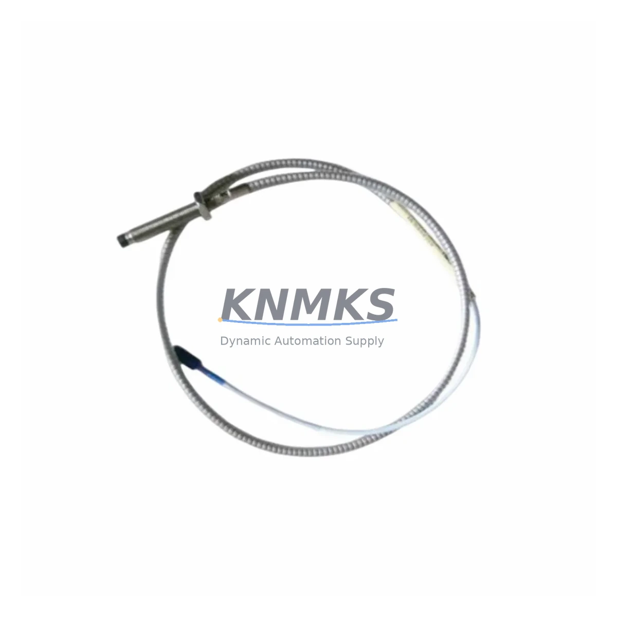
Bently Nevada 330104-00-15-05-02-00 3300 XL Spare Part: Maintenance-Proven Proximity Probe for Factory Uptime
The Bently Nevada 330104-00-15-05-02-00 is an 8mm eddy-current proximity probe engineered for the 3300 XL continuous vibration monitoring system. In rotating machinery environments — turbines, compressors, pumps, and gearboxes — this probe is the primary sensor responsible for shaft radial vibration, axial position, and differential expansion measurement. When this component fails or degrades, the entire protection loop is compromised, and unplanned downtime becomes unavoidable. Maintaining a verified spare on the shelf is the single most effective action a maintenance team can take to reduce mean time to repair (MTTR) and protect production continuity.
This listing covers the original Bently Nevada 330104-00-15-05-02-00 proximity probe: 5-metre integral cable, 8mm tip diameter, standard -18 Vdc supply, and a linear range calibrated for the 3300 XL signal conditioner chain. Each unit is pre-shipment tested against OEM electrical specifications before dispatch. A support terms confirmed by quotation is included from the date of shipment.
Spare Maintenance Table
| Parameter | Specification |
|---|---|
| Part Number | 330104-00-15-05-02-00 |
| Series | Bently Nevada 3300 XL |
| Probe Type | Eddy-Current Proximity Probe (8mm) |
| Cable Length | 5 metres (integral) |
| Supply Voltage | -18 Vdc (nominal), -24 Vdc (max) |
| Output Sensitivity | 7.87 V/mm (200 mV/mil) |
| Linear Range | 0.25 mm – 2.26 mm (10 – 89 mil) |
| Temperature Range | -35°C to +177°C (probe tip) |
| Target Material | AISI 4140 steel or equivalent |
| Compatible Monitor | Bently Nevada 3300 XL Series |
| Compatible Driver/Conditioner | 330180 / 330130 proximitor extension cable system |
| Country of Origin | United States |
| Condition | Original / OEM-equivalent, pre-shipment tested |
| Support terms | 12 Months from shipment date |
| Application | Radial vibration, axial position, differential expansion — turbines, compressors, pumps, gearboxes |
| Maintenance Interval | Inspect gap voltage at every scheduled outage; replace probe if sensitivity drift exceeds ±5% |
Maintenance Planning for Continuous Operation
A proximity probe does not operate in isolation. The 330104-00-15-05-02-00 is one node in a complete measurement chain, and a fault anywhere in that chain produces the same symptom: loss of valid vibration signal. When replacing this probe during a planned or emergency outage, maintenance engineers should simultaneously inspect and verify the following associated components to avoid repeat call-outs.
The 330130 proximitor extension cable connects the probe to the proximitor and is subject to jacket cracking, connector corrosion, and shield continuity loss in high-temperature or high-vibration environments. A degraded extension cable will produce gap voltage drift indistinguishable from a failing probe. Always measure cable insulation resistance and shield continuity before condemning the probe itself.
The 330180 proximitor sensor (or its equivalent in the 3300 XL driver chain) converts the probe’s impedance change into a calibrated DC voltage. If the proximitor supply rail is outside the -18 Vdc ±1 Vdc tolerance, probe sensitivity will shift and alarm setpoints will be unreliable. Verify the proximitor output voltage and replace the unit if it falls outside specification.
The 3300/16 or 3300/20 monitor card housed in the 3300 XL rack receives the conditioned signal. During a probe replacement, confirm that the monitor card’s OK relay is healthy and that the channel is not latched in a fault state from a previous trip. A latched channel will mask a successful probe installation during commissioning.
The 3300 XL rack power supply module — typically a dual-redundant -24 Vdc supply — should be load-tested during any major outage. A sagging supply rail is a common root cause of intermittent probe OK dropouts that are misdiagnosed as probe failures. Spare power supply modules for the 3300 XL rack are a high-priority item for any critical machinery protection inventory.
For installations where the probe signal is also routed to a DCS analog input card or a safety instrumented system (SIS) input module, verify that the 4–20 mA or voltage signal at the DCS terminal strip is within the expected range after probe replacement. Signal isolators or barriers in this path should be inspected for drift, particularly in older installations where the isolator may be approaching end of service life.
Finally, review the terminal block wiring and cable gland integrity at the junction box nearest the machine. Loose terminations and ingress of process fluids at the gland are among the most common causes of nuisance trips in proximity probe circuits and are easily addressed during the same work order as a probe replacement.
Site Replacement Workflow
Step 1 — Permit and isolation. Obtain a hot-work or cold-work permit as required by site procedures. Confirm that the monitor channel is bypassed or that the machinery protection system is in maintenance mode to prevent a spurious trip during probe removal.
Step 2 — Gap voltage baseline. Before removing the existing probe, record the gap voltage displayed on the 3300 XL monitor or read directly at the proximitor output. A healthy gap voltage for the 330104-00-15-05-02-00 at the nominal 1.0 mm installation gap is approximately -10.0 Vdc. Significant deviation from this value confirms the probe or extension cable is the fault source.
Step 3 — Probe removal. Loosen the probe locknut and back the probe out carefully. Inspect the probe tip for physical damage, contamination, or oil carbonisation. Inspect the target area on the shaft for scoring or pitting that could affect the new probe’s linear range.
Step 4 — New probe installation. Thread the 330104-00-15-05-02-00 replacement into the bracket. Set the gap to the OEM-specified value (typically 1.0 mm / 40 mil for this series) using a non-ferrous feeler gauge or a calibrated gap-setting tool. Tighten the locknut to the specified torque.
Step 5 — Gap voltage verification. With the proximitor energised, confirm the gap voltage is within the linear range (-9.5 to -10.5 Vdc at 1.0 mm gap). Adjust gap if necessary. Document the final gap voltage in the maintenance record.
Step 6 — System reinstatement. Remove the bypass, confirm the monitor channel returns to OK status, and verify that the vibration reading is stable and consistent with historical baseline values. Return the permit and update the equipment history card.
This workflow applies equally to scheduled annual overhauls, emergency replacements during unplanned outages, and proactive swap-outs triggered by predictive maintenance trending. Keeping a pre-tested 330104-00-15-05-02-00 spare on site reduces the replacement cycle from days (procurement lead time) to hours (installation time), which is the most direct lever available to maintenance teams for improving machinery availability.
Spare Parts Support FAQ
Q1: Is the 330104-00-15-05-02-00 compatible with older 3300 series monitors, not just the 3300 XL?
The 330104-00-15-05-02-00 is calibrated and specified for the 3300 XL system. While the physical connector and cable format are similar to earlier 3300 series probes, sensitivity and linear range are optimised for the XL proximitor chain. Cross-compatibility with non-XL monitors should be verified against the specific monitor card’s input specification before installation. Contact our technical team with your monitor card part number for confirmation prior to ordering.
Q2: What pre-shipment testing is performed on each unit?
Each 330104-00-15-05-02-00 unit is electrically tested before dispatch: gap voltage linearity across the full linear range, cable insulation resistance, shield continuity, and connector integrity are all verified. A test record is available on request. This process ensures that the spare you receive is ready for immediate installation without additional bench testing on site.
Q3: How many spares should a site carry for critical rotating machinery?
Industry best practice for critical machinery (turbines, main compressors, boiler feed pumps) is a minimum of one spare probe per monitored channel, plus one additional unit per machine train as a buffer. For a typical 3300 XL installation monitoring two radial channels and one axial channel per bearing, this means three to four 330104-00-15-05-02-00 units per machine. Sites with long procurement lead times or remote locations should consider a higher buffer quantity.
Q4: What is the long-term supply commitment and support terms coverage?
We maintain ongoing stock of the 330104-00-15-05-02-00 to support legacy 3300 XL installations that may no longer be covered by OEM active production. All units carry a support terms confirmed by quotation from the shipment date, covering manufacturing defects and electrical performance against the stated specification. For sites requiring a multi-year supply agreement or blanket purchase order arrangement, contact our sales team to discuss volume pricing and reserved stock options.
© 2026 KNMKS. All rights reserved.
Original Source: https://knmks.com
Contact: admin@knmks.com | +86 18359268345
Product Identification
- Brand / Ecosystem
-
Bently Nevada
Bently Nevada - Model / Series
-
330104-00-15-05-02-00
Bently Nevada 3300 XL / 3301 Series - Product Family
- Sensors
- Availability Status
- Available on request after model and quantity confirmation
- Inquiry Type
- B2B RFQ, replacement inquiry and project spare-part request
- Pre-Quote Check
- Exact SKU, brand, series, quantity, nameplate photos and destination country are checked before quotation
System Path
Where this product fits in the KNMKS automation structure.
Specification & Inquiry Focus
- Sensor range
- Photoelectric, proximity and process sensors
- Common needs
- Output type, distance and connector
- Project support
- Machine detection and replacement inquiry
Buyer Confirmation
Information KNMKS checks before replying.
- Exact model
- 330104-00-15-05-02-00
- Brand / ecosystem
- Bently Nevada
- Product family
- Sensors
- Application note
- Replacement, maintenance, project build or spare-part list
- Useful photos
- Nameplate, installed unit, cabinet layout or connector side
- Delivery details
- Quantity, destination country and target schedule
Document Support
Files and notes can be confirmed during quotation.
- Product photos or nameplate confirmation when available
- Packing and delivery notes before quotation confirmation
- Support scope and delivery terms confirmed per inquiry
- Export document coordination for qualified B2B requests
Inquiry Support
- NPN/PNP, analog and digital output checking
- Connector and cable compatibility review
- Fast inquiry support for maintenance teams
What to Send Us
- Brand and exact model number: Bently Nevada 330104-00-15-05-02-00
- Quantity and required delivery time
- Application, replacement requirement or nameplate photo
- Destination country and shipping preference
RFQ Preparation
This is a product inquiry page built for RFQ communication.
Fast Model Check
Send this model to KNMKS for confirmation.
Include quantity, destination country and photos if this is a maintenance replacement. The inquiry will be saved with a reference number after submission.
Brand & Compatibility Note
KNMKS displays automation product information for well-known industrial brand ecosystems and compatible replacement references. Brand names are used for product identification and compatibility reference only; final availability and commercial terms are confirmed per quotation.
 Manufacturing
 Machine Tools
 Packaging
 Energy & Power



 PLCs & Controllers
 HMI & Displays
 Servo Systems
 Variable Frequency Drives