
Overview
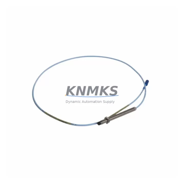
Bently Nevada 330104-00-11-10-02-CN 3300 XL Maintenance-Proven Spare Part for Factory Uptime
The Bently Nevada 330104-00-11-10-02-CN is an 11mm eddy-current proximity probe belonging to the industry-standard 3300 XL Series, engineered for continuous vibration and position monitoring on turbines, compressors, pumps, and other critical rotating machinery. As a maintenance-proven spare part, this probe is a cornerstone of predictive maintenance programs in power generation, oil & gas, petrochemical, and heavy manufacturing facilities worldwide. Keeping a verified OEM-grade replacement in your spare parts inventory is one of the most effective strategies to minimize unplanned downtime and protect high-value rotating assets.
Maintenance engineers and procurement teams rely on the 330104-00-11-10-02-CN for its consistent output sensitivity, robust stainless-steel housing, and direct compatibility with Bently Nevada 3300 XL signal conditioning systems. Whether you are executing a planned annual overhaul, responding to a vibration alarm, or building a strategic spare parts buffer for a multi-train facility, this probe delivers the dimensional and electrical consistency required for drop-in replacement without recalibration of the monitoring system.
Spare Maintenance Table
| Parameter | Specification |
|---|---|
| SKU / Part Number | 330104-00-11-10-02-CN |
| Brand | Bently Nevada |
| Series | 3300 XL |
| Product Type | Eddy-Current Proximity Transducer (Probe) |
| Probe Tip Diameter | 11 mm |
| Cable Length | 1.0 m (standard) |
| Connector Type | CN (Coaxial, standard Bently Nevada) |
| Output Sensitivity | 7.87 V/mm (200 mV/mil) nominal |
| Operating Temperature | -35°C to +121°C |
| Supply Voltage | -24 VDC (via driver/extension cable) |
| Compatibility | Bently Nevada 3300 XL Proximitor® Sensor, 3300 XL 8mm/11mm signal conditioners |
| Installation | Threaded mounting, M14 x 1.0 (standard), direct replacement for 330104 series |
| Application Environment | Turbines, compressors, pumps, gearboxes, motors — oil & gas, power, petrochemical |
| Maintenance Recommendation | Inspect probe tip, extension cable, and driver at each planned outage; replace as a matched set when gap voltage drifts beyond ±0.5 V of baseline |
| Support terms | 12 Months from date of shipment |
| Origin | USA (OEM) |
Maintenance Planning for Continuous Operation
A proximity probe does not operate in isolation. The 330104-00-11-10-02-CN is one element of a complete measurement chain, and a disciplined maintenance plan must account for every link in that chain to ensure reliable vibration data and avoid nuisance trips or missed fault detection.
When replacing or inspecting the 330104-00-11-10-02-CN, maintenance engineers should simultaneously verify the condition of the 330130-045-00-00 extension cable (or equivalent 3300 XL armored extension), which connects the probe to the Proximitor® driver. Cable jacket abrasion, connector corrosion, or impedance mismatch caused by a damaged extension cable will produce erratic gap voltage readings that can be misdiagnosed as a probe failure. The 330180-X1-05 Proximitor® sensor (driver module) should be bench-tested for output linearity whenever a probe is replaced — a degraded driver is a common root cause of recurring probe alarms.
Inside the control cabinet, the 3500/42M Proximitor®/Seismic Monitor I/O module and its associated terminal blocks should be inspected for loose wiring, oxidized contacts, and correct channel configuration. If the facility uses a 3500/20 rack power supply, verify that output voltage is within specification under full load, as low supply voltage directly affects probe sensitivity and gap voltage calibration. For plants running older 3300 series racks alongside newer 3500 systems, confirm that the signal conditioner firmware and channel configuration are compatible with the 11mm probe sensitivity curve.
Procurement engineers building annual spare parts lists for rotating machinery should consider stocking the 330104-00-11-10-02-CN alongside matched extension cables, at least one spare Proximitor® driver per critical train, and a set of 3500 rack fuses and power supply modules. For facilities with multiple identical trains, a minimum of two probe assemblies per train per year is a widely accepted inventory benchmark. Where HMI-based condition monitoring is in use, ensure that the System 1 Evolution software configuration reflects the correct probe type and gap voltage range to avoid false alarms following replacement.
Signal isolation barriers and surge protection devices installed between the field wiring and the monitor rack should also be inspected during any probe replacement activity. Transient voltage events in industrial environments can damage probe electronics without leaving visible physical evidence, making periodic replacement of surge protection components a cost-effective insurance measure for high-criticality assets.
Site Replacement Workflow
Step 1 — Pre-Replacement Verification: Before removing the existing probe, record the current gap voltage from the monitor display or System 1 trend data. This baseline value confirms the probe is within its linear range and provides a reference for post-installation verification of the replacement unit.
Step 2 — Isolation and Lockout: Follow site LOTO procedures. Disconnect the extension cable at the Proximitor® driver. Do not disconnect at the probe end while the machine is running, as this will generate a full-scale alarm in the monitor.
Step 3 — Probe Removal: Using the correct spanner, unthread the 330104-00-11-10-02-CN from the probe holder. Inspect the probe tip for impact damage, pitting, or contamination. Inspect the probe holder threads and the target surface for wear or runout anomalies.
Step 4 — Installation of Replacement: Thread the new 330104-00-11-10-02-CN into the probe holder. Set the initial gap to the manufacturer-recommended starting distance (typically 1.0–1.5 mm for 11mm probes). Reconnect the extension cable, ensuring the connector is fully seated and the locking ring is secure.
Step 5 — Gap Voltage Confirmation: With the machine at rest and the monitor powered, read the gap voltage. Adjust probe depth until the gap voltage matches the system baseline (typically -10 to -11 VDC for mid-range gap on a 3300 XL system). Lock the probe in position with the locknut.
Step 6 — Functional Test and Documentation: Restore the machine to service and monitor vibration and position readings through the first startup transient. Document the replacement in the maintenance management system, including the new probe serial number, installation date, and post-installation gap voltage. This record supports support requests and future trend analysis.
This workflow supports direct replacement of legacy 330104 series probes without modification to the monitor rack or software configuration, preserving system compatibility and reducing total downtime to under two hours for a trained technician.
Spare Parts Support FAQ
Q1: Is the 330104-00-11-10-02-CN compatible with both 3300 XL and 3500 series monitor racks?
Yes. The 330104-00-11-10-02-CN is designed for the 3300 XL measurement chain and is fully compatible with 3500 series monitor racks when used with the correct 3300 XL Proximitor® sensor. Always verify channel configuration in the monitor software to ensure the probe sensitivity curve (7.87 V/mm) is correctly selected before returning the machine to service.
Q2: What is the recommended inventory quantity for a critical rotating machinery application?
Industry best practice for critical assets such as steam turbines or centrifugal compressors is to maintain a minimum of two spare probe assemblies per monitored shaft, plus one spare matched extension cable and one spare Proximitor® driver per train. For facilities with multiple identical trains, consolidated spare parts pooling can reduce total inventory cost while maintaining adequate coverage.
Q3: How is the 330104-00-11-10-02-CN tested before shipment?
Each unit undergoes electrical continuity verification, insulation resistance testing, and gap voltage linearity confirmation against a calibrated reference target prior to packaging. Units are shipped with individual test records. The support terms confirmed by quotation cover manufacturing defects and electrical performance deviations from published specifications under normal operating conditions.
Q4: Can this probe replace older 330104 variants with different cable or connector suffixes?
The 330104 series uses a standardized suffix structure where the connector type (CN = standard coaxial) and cable length are encoded in the part number. The -CN suffix is the most widely deployed variant and is mechanically and electrically interchangeable with other 330104 assemblies of the same probe tip diameter, provided the extension cable and driver are also matched to the 3300 XL specification. Consult the Bently Nevada 3300 XL installation manual or contact our technical team to confirm compatibility for non-standard configurations.
© 2026 KNMKS. All rights reserved.
Original Source: https://knmks.com
Contact: admin@knmks.com | +86 18359268345
Product Identification
- Brand / Ecosystem
-
Bently Nevada
Bently Nevada - Model / Series
-
330104-00-11-10-02-CN
Bently Nevada 3300 XL / 3301 Series - Product Family
- Sensors
- Availability Status
- Available on request after model and quantity confirmation
- Inquiry Type
- B2B RFQ, replacement inquiry and project spare-part request
- Pre-Quote Check
- Exact SKU, brand, series, quantity, nameplate photos and destination country are checked before quotation
System Path
Where this product fits in the KNMKS automation structure.
Specification & Inquiry Focus
- Sensor range
- Photoelectric, proximity and process sensors
- Common needs
- Output type, distance and connector
- Project support
- Machine detection and replacement inquiry
Buyer Confirmation
Information KNMKS checks before replying.
- Exact model
- 330104-00-11-10-02-CN
- Brand / ecosystem
- Bently Nevada
- Product family
- Sensors
- Application note
- Replacement, maintenance, project build or spare-part list
- Useful photos
- Nameplate, installed unit, cabinet layout or connector side
- Delivery details
- Quantity, destination country and target schedule
Document Support
Files and notes can be confirmed during quotation.
- Product photos or nameplate confirmation when available
- Packing and delivery notes before quotation confirmation
- Support scope and delivery terms confirmed per inquiry
- Export document coordination for qualified B2B requests
Inquiry Support
- NPN/PNP, analog and digital output checking
- Connector and cable compatibility review
- Fast inquiry support for maintenance teams
What to Send Us
- Brand and exact model number: Bently Nevada 330104-00-11-10-02-CN
- Quantity and required delivery time
- Application, replacement requirement or nameplate photo
- Destination country and shipping preference
RFQ Preparation
This is a product inquiry page built for RFQ communication.
Fast Model Check
Send this model to KNMKS for confirmation.
Include quantity, destination country and photos if this is a maintenance replacement. The inquiry will be saved with a reference number after submission.
Brand & Compatibility Note
KNMKS displays automation product information for well-known industrial brand ecosystems and compatible replacement references. Brand names are used for product identification and compatibility reference only; final availability and commercial terms are confirmed per quotation.
 Manufacturing
 Machine Tools
 Packaging
 Energy & Power



 PLCs & Controllers
 HMI & Displays
 Servo Systems
 Variable Frequency Drives