
Overview
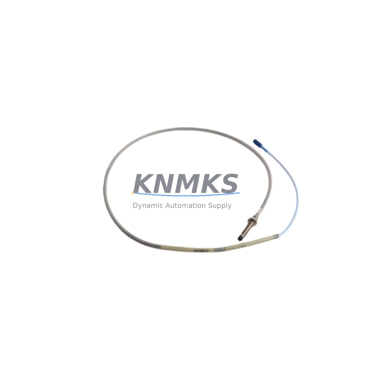
Bently Nevada 330104-00-05-90-02-05 Migration-Ready Proximity Probe for Legacy Control Systems
The Bently Nevada 330104-00-05-90-02-05 is an 8mm eddy-current proximity probe designed for the 3300 XL Series vibration monitoring platform. As legacy rotating machinery protection systems approach end-of-life, this probe serves as a direct, migration-ready replacement for discontinued 330104-series variants, enabling engineers to restore full vibration monitoring capability without redesigning the measurement chain or rewriting monitor configuration logic.
Engineered to the same dimensional and electrical specification as the original factory part, the 330104-00-05-90-02-05 maintains a 5-metre integral cable, a 90-mil (2.29 mm) tip-to-target gap range, and a –24 VDC bias voltage output compatible with the 3300 XL Monitor, the 3500/42M Proximitor I/O Module, and the 3500/22M Transient Data Interface. Engineers migrating from earlier 330104-00-05-05-02-05 or 330104-00-05-05-CN-05 configurations will find the connector pinout, sensitivity (200 mV/mil), and cable jacket specification unchanged, eliminating the need for terminal block rewiring or signal scaling adjustments in the monitor.
Migration Compatibility Table
| Parameter | 330104-00-05-90-02-05 | Legacy / Replaced Models | Retrofit Note |
|---|---|---|---|
| Probe Diameter | 8 mm | 8 mm | No housing modification required |
| Cable Length | 5 m (integral) | 5 m | Extension cable 330130-080-00-00 may be reused |
| Sensitivity | 200 mV/mil (7.87 V/mm) | 200 mV/mil | No rescaling in 3300 XL Monitor required |
| Bias Voltage Output | –24 VDC (nominal) | –24 VDC | Compatible with 3500/42M I/O module |
| Gap Range | 0.25 – 2.29 mm (10 – 90 mil) | 10 – 90 mil | Re-gap to 50 mil (1.27 mm) nominal during installation |
| Connector Type | Integral coaxial | Integral coaxial | Direct mate to Proximitor extension cable |
| Compatible Monitor | 3300 XL, 3500/42M, 3500/22M | 3300 XL, 3500 Series | Verify firmware ≥ Rev D on 3500/42M |
| Installation Space | Standard 8 mm probe boss | Standard 8 mm probe boss | No machining required |
| Communication / Output | Analog voltage (passive) | Analog voltage | No protocol migration needed |
| Support terms | support terms confirmed by quotation — covers manufacturing defects, sensitivity drift, and connector integrity | ||
Retrofit Planning for Existing Automation Systems
A successful retrofit of the 330104-00-05-90-02-05 into an operating turbine or compressor protection loop requires a structured pre-installation review. Begin by auditing the existing Proximitor/Seismoprobe extension cable — typically a 330130-series cable — to confirm it is free of shield damage and that the coaxial connector is clean and undamaged. A degraded extension cable will introduce noise into the –24 VDC signal path and cause false OK/Not-OK transitions at the 3300 XL Monitor or 3500/42M Proximitor I/O Module, even with a new probe installed.
Next, verify the power supply feeding the Proximitor system. The 3300 XL Proximitor requires a regulated –24 VDC supply with less than 50 mV peak-to-peak ripple. If the control cabinet houses an aging 3300/20 Power Supply Module, this is an appropriate time to evaluate its output quality with a calibrated oscilloscope before committing to probe replacement. A marginal power supply will mask the improvement delivered by a new probe and may cause nuisance trips during commissioning.
For systems running the 3500 Series rack, confirm that the 3500/42M Proximitor I/O Module channel configuration matches the probe’s 200 mV/mil sensitivity and 8 mm tip diameter. The 3500 rack’s configuration software (Rack Configuration Utility) stores these parameters per channel; an incorrect sensitivity entry will produce erroneous vibration readings in the DCS historian and any connected HMI display — whether a System 1 Evolution workstation or a third-party SCADA screen mapped to the 3500’s Modbus TCP or EtherNet/IP output registers.
Where the plant’s control architecture includes a 3500/92 Communication Gateway Module for Modbus or OPC-DA integration, no protocol reconfiguration is required when replacing a like-for-like 330104-series probe. The gateway continues to publish the same register map to the DCS or historian. However, if the retrofit is part of a broader migration from a 3300 XL standalone rack to a 3500 Series integrated rack, the Modbus register addresses will shift and the DCS I/O mapping must be updated before the new rack is energised.
I/O wiring at the terminal block should be documented with as-found photographs before disconnection. The probe’s integral cable terminates at the Proximitor input; the Proximitor’s output terminals connect to the 3500/42M I/O module or directly to the 3300 XL Monitor’s BNC or terminal strip input. Label each conductor before removal and verify continuity after reconnection with a calibrated multimeter. Do not rely on colour coding alone — cable jackets on aged installations frequently fade or have been field-repaired with non-standard materials.
Finally, if the plant operates a 3500/53 Overspeed Detection Module or a 3500/33 16-Channel Relay Module in the same rack, confirm that the relay setpoints and time delays stored in those modules are backed up to the Rack Configuration Utility before any power interruption. Probe replacement does not affect these modules directly, but a rack power cycle during installation provides an opportunity to verify that all module configurations are current and match the approved cause-and-effect matrix.
Downtime Control During System Migration
Minimising unplanned downtime during a proximity probe replacement begins with a bypass and inhibit strategy agreed upon with the operations team before the maintenance window opens. On a 3500 Series rack, the 3500/42M Proximitor I/O Module supports a software inhibit function accessible through the Rack Configuration Utility or, where licensed, through System 1 Evolution. Activating the inhibit on the affected channel suppresses the OK relay and prevents a spurious trip to the 3500/33 Relay Module while the probe is disconnected and re-gapped.
For 3300 XL standalone installations without software inhibit, a hardwired bypass relay inserted at the monitor’s relay output terminals achieves the same result. Document the bypass state in the permit-to-work system and set a time limit — typically 30 minutes for a straightforward probe swap — to prevent the bypass from being left in place beyond the maintenance window.
Once the 330104-00-05-90-02-05 is installed and the gap set to 50 mil (1.27 mm) nominal using a non-ferrous feeler gauge, verify the DC bias voltage at the Proximitor output terminals before releasing the inhibit. A reading of –10.0 VDC ± 0.5 VDC at the nominal gap confirms correct probe-Proximitor interaction. If the reading falls outside this range, re-check the extension cable connection and the probe tip for contamination before proceeding.
After releasing the inhibit, monitor the vibration trend in the DCS historian or System 1 Evolution for a minimum of 15 minutes at operating speed to confirm that the 1X and 2X vibration vectors are stable and consistent with the pre-replacement baseline. Any step change greater than 10% in the overall vibration level warrants investigation before returning the machine to normal operation. This structured commissioning sequence protects the original program logic, maintains field control continuity, and reduces retrofit risk to the lowest practical level.
Retrofit Support FAQ
Q1: Is the 330104-00-05-90-02-05 a direct replacement for the 330104-00-05-05-02-05?
Yes. Both probes share the same 8 mm tip diameter, 200 mV/mil sensitivity, –24 VDC bias output, and integral coaxial connector. The suffix difference (90 vs 05) denotes the gap range specification; the 90-mil variant covers the same 10–90 mil measurement range used in standard turbine and compressor applications. No rewiring, rescaling, or monitor reconfiguration is required for a direct substitution.
Q2: What commissioning checks are required after installation?
After installation, verify the DC gap voltage (–10.0 VDC ± 0.5 VDC at 50 mil nominal gap), confirm the OK LED status on the 3300 XL Monitor or 3500/42M I/O Module, and review the vibration trend in the DCS or System 1 Evolution for at least 15 minutes at operating speed. Record the as-left gap voltage and vibration baseline in the maintenance management system for future reference.
Q3: Does this probe require any firmware update on the 3500/42M module?
The 330104-00-05-90-02-05 is compatible with all production firmware revisions of the 3500/42M Proximitor I/O Module. However, Bently Nevada recommends that the module firmware be at Rev D or later to ensure full support for the inhibit function and the extended diagnostics available through the Rack Configuration Utility. Firmware version can be confirmed in the module’s front-panel display or through the configuration software.
Q4: What is the support terms coverage and stock availability?
All 330104-00-05-90-02-05 units supplied by KNMKS carry a support terms confirmed by quotation covering manufacturing defects, sensitivity drift beyond ±2% of nominal, and connector integrity. Stock is maintained for immediate dispatch; lead time for in-stock units is typically 3–5 business days to most destinations. For critical spares programmes or long-term supply commitments, contact the KNMKS sales team to discuss consignment or reserved inventory arrangements.
© 2026 KNMKS. All rights reserved.
Original Source: https://knmks.com
Contact: admin@knmks.com | +86 18359268345
Product Identification
- Brand / Ecosystem
-
Bently Nevada
Bently Nevada - Model / Series
-
330104-00-05-90-02-05
Bently Nevada 3300 XL / 3301 Series - Product Family
- Sensors
- Availability Status
- Available on request after model and quantity confirmation
- Inquiry Type
- B2B RFQ, replacement inquiry and project spare-part request
- Pre-Quote Check
- Exact SKU, brand, series, quantity, nameplate photos and destination country are checked before quotation
System Path
Where this product fits in the KNMKS automation structure.
Specification & Inquiry Focus
- Sensor range
- Photoelectric, proximity and process sensors
- Common needs
- Output type, distance and connector
- Project support
- Machine detection and replacement inquiry
Buyer Confirmation
Information KNMKS checks before replying.
- Exact model
- 330104-00-05-90-02-05
- Brand / ecosystem
- Bently Nevada
- Product family
- Sensors
- Application note
- Replacement, maintenance, project build or spare-part list
- Useful photos
- Nameplate, installed unit, cabinet layout or connector side
- Delivery details
- Quantity, destination country and target schedule
Document Support
Files and notes can be confirmed during quotation.
- Product photos or nameplate confirmation when available
- Packing and delivery notes before quotation confirmation
- Support scope and delivery terms confirmed per inquiry
- Export document coordination for qualified B2B requests
Inquiry Support
- NPN/PNP, analog and digital output checking
- Connector and cable compatibility review
- Fast inquiry support for maintenance teams
What to Send Us
- Brand and exact model number: Bently Nevada 330104-00-05-90-02-05
- Quantity and required delivery time
- Application, replacement requirement or nameplate photo
- Destination country and shipping preference
RFQ Preparation
This is a product inquiry page built for RFQ communication.
Fast Model Check
Send this model to KNMKS for confirmation.
Include quantity, destination country and photos if this is a maintenance replacement. The inquiry will be saved with a reference number after submission.
Brand & Compatibility Note
KNMKS displays automation product information for well-known industrial brand ecosystems and compatible replacement references. Brand names are used for product identification and compatibility reference only; final availability and commercial terms are confirmed per quotation.
 Manufacturing
 Machine Tools
 Packaging
 Energy & Power



 PLCs & Controllers
 HMI & Displays
 Servo Systems
 Variable Frequency Drives