
Overview
Bently Nevada 330103-19-25-05-02-CN Migration-Ready Proximity Transducer for Legacy Control Systems
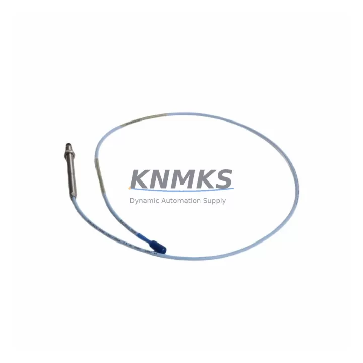
The Bently Nevada 330103-19-25-05-02-CN is a high-precision eddy-current proximity transducer engineered for the 3300 XL Series monitoring platform. As legacy vibration monitoring systems approach end-of-life and OEM support is discontinued, this unit serves as a verified drop-in replacement for aging 330103-series transducers installed across turbomachinery, compressor trains, and rotating equipment protection systems worldwide. Whether you are executing a planned retrofit, responding to an unplanned failure, or building a strategic spare-parts inventory to extend the operational life of your existing 3300 XL infrastructure, the 330103-19-25-05-02-CN delivers the dimensional, electrical, and signal-chain compatibility required to restore full system functionality with minimal engineering intervention.
This transducer operates within the standard Bently Nevada eddy-current measurement chain. It is designed to work in conjunction with the 330130 extension cable and the 3300 XL 8mm Proximitor® sensor driver, forming a complete proximity measurement loop that integrates directly into existing 3500 Series rack-based monitoring systems or standalone 3300 XL field-mount enclosures. When replacing a failed or degraded transducer in a live installation, engineers should verify the gap voltage at the Proximitor output — typically –10.0 VDC at the calibrated gap — before returning the machine to service. The 330103-19-25-05-02-CN maintains the same 8mm tip diameter, 5-metre integral cable, and –24 VDC bias voltage specification as the original factory-installed units, eliminating the need for cable splicing, bracket modification, or driver reconfiguration in most retrofit scenarios.
Migration Compatibility Table
| Parameter | 330103-19-25-05-02-CN | Legacy / Replaced Unit | Retrofit Notes |
|---|---|---|---|
| Tip Diameter | 8 mm | 8 mm | No bracket modification required |
| Cable Length | 5 m (integral) | 5 m | Match with 330130 extension cable if longer run needed |
| Bias Voltage | –24 VDC | –24 VDC | Compatible with existing 3300 XL Proximitor driver |
| Output Sensitivity | 7.87 V/mm (200 mV/mil) | 7.87 V/mm | No recalibration of monitoring rack required |
| Linear Range | 0.25 – 2.26 mm (10 – 89 mil) | Same | Verify installed gap is within linear range post-installation |
| Communication Protocol | Analogue (4–20 mA / voltage) | Analogue | No protocol migration required; direct signal-chain replacement |
| Rack Compatibility | 3500 Series / 3300 XL | 3500 / 3300 XL | Slot-compatible; no firmware update required on monitor card |
| Installation Space | Standard 8 mm probe mount | Same | Confirm probe holder thread: M10 × 1 standard |
| Firmware Dependency | None (passive transducer) | None | Driver firmware version does not affect transducer replacement |
| Support terms | 12 Months from shipment date | Covers manufacturing defects and signal-chain performance | |
Retrofit Planning for Existing Automation Systems
Successful integration of the 330103-19-25-05-02-CN into a legacy rotating equipment protection system requires a structured pre-installation review. Begin by auditing the existing Proximitor® sensor — typically a 330180 or 330100 Series driver — to confirm that the driver’s input impedance and supply voltage remain within specification. A degraded driver will produce erratic gap voltage readings even with a new transducer installed, so replacing the transducer alone may not resolve intermittent alarms if the driver has accumulated moisture ingress or connector corrosion over years of field service.
Next, inspect the 330130 extension cable that bridges the transducer to the Proximitor. Extension cables are a common failure point in high-vibration environments; damaged shielding introduces noise into the measurement loop and can cause false danger or alert trips in the 3500/40M or 3500/42M monitor cards housed in the 3500 Series rack. If the extension cable shows any sign of jacket cracking, connector fretting, or shield continuity loss, it should be replaced concurrently with the transducer to avoid a repeat outage.
At the rack level, verify that the 3500 Series monitor card assigned to this measurement channel is configured for the correct transducer type and gap range. The 3500 rack’s configuration software — accessed via the 3500 Rack Configuration Utility — stores channel-level parameters including OK limit voltages, danger setpoints, and transducer scale factors. These parameters do not need to be changed when replacing a like-for-like 330103-series transducer, but they should be documented before any work begins so that the as-found configuration can be restored if a rack power cycle resets non-volatile memory on older firmware revisions.
For installations where the 3300 XL system feeds vibration data to a DCS or safety instrumented system via a 4–20 mA analogue output, confirm that the loop receiver — whether a Yokogawa, Honeywell, or Emerson DCS I/O card — is still reading within the expected engineering unit range after the transducer swap. A shift in the analogue output of more than ±0.1 mA at the calibrated gap position should be investigated before the machine is returned to automatic control. In plants where the vibration signal also drives an HMI faceplate or historian tag, coordinate with the control room operator to verify that the displayed gap value and vibration amplitude match the field measurement after installation.
Downtime Control During System Migration
Minimising unplanned downtime during a proximity transducer replacement begins with pre-staging all replacement components before the machine is taken offline. For the 330103-19-25-05-02-CN, this means having the transducer, the matching 330130 extension cable, and a calibrated gap-setting tool available at the work site before the isolation permit is issued. A pre-staged replacement reduces the active outage window to the time required for mechanical removal, installation, gap setting, and signal verification — typically 45 to 90 minutes for a single measurement point on an accessible bearing housing.
To protect the original program logic and monitoring configuration, export the 3500 rack configuration file before beginning any hardware work. This file captures all channel setpoints, OK limits, danger bypass states, and communication parameters. If the rack loses power during the replacement — for example, during a full control cabinet shutdown required to access a confined probe location — the configuration file allows the system to be restored to its exact pre-outage state without manual re-entry of setpoints, which is a significant source of commissioning errors in time-pressured outage environments.
Where the machine cannot be fully stopped, some plants perform a hot-swap of the transducer by placing the affected monitoring channel into bypass mode at the 3500 rack before disconnecting the field device. This approach maintains the safety function of the remaining channels while the failed transducer is replaced, and it avoids a spurious trip that could cascade into a broader process shutdown. Bypass mode should be time-limited, documented in the permit-to-work system, and cleared immediately after the replacement transducer has been verified at the correct gap voltage. All steps should be confirmed with the site’s functional safety engineer before proceeding in SIL-rated applications.
Retrofit Support FAQ
Q1: Is the 330103-19-25-05-02-CN a direct replacement for other 330103-series part numbers?
A: The 330103-19-25-05-02-CN is dimensionally and electrically compatible with other 330103-series variants that share the 8 mm tip diameter and 5-metre cable length. The suffix digits encode the cable length, connector type, and approval markings, so confirm that the suffix of the unit being replaced matches the installation requirements — particularly the connector style and any hazardous-area certification needed for the specific probe location. Units are pre-tested and gap-verified before shipment.
Q2: What commissioning checks are required after installation?
A: After mechanical installation, set the probe gap to the manufacturer’s recommended value (typically 1.0 mm / 40 mil for most 8 mm applications) and measure the Proximitor output voltage. The output should read approximately –10.0 VDC ±0.5 VDC at the calibrated gap. Confirm that the 3500 monitor card shows an OK status and that the vibration reading is within the expected baseline range for the machine at rest. Clear any latched alerts or danger conditions at the rack before releasing the machine to operations.
Q3: Can this transducer be used with third-party Proximitor-compatible drivers?
A: The 330103-19-25-05-02-CN is designed and calibrated for use with Bently Nevada Proximitor drivers. While the eddy-current operating principle is industry-standard, sensitivity and linearity specifications are optimised for the Bently Nevada driver supply voltage and input impedance. Use with third-party drivers may result in measurement errors and is not recommended without independent field calibration. Contact our technical team for guidance on mixed-platform installations.
Q4: What is the support terms coverage and what does the stock availability look like?
A: All units supplied by KNMKS carry a support terms confirmed by quotation from the date of shipment, covering manufacturing defects and signal-chain performance under normal operating conditions. We maintain dedicated inventory of 330103-series transducers to support emergency replacement and planned maintenance programmes. Same-day dispatch is available for in-stock units, and we can provide a certificate of conformance and test report upon request. Contact our team for current lead times and volume pricing.
© 2026 KNMKS. All rights reserved.
Original Source: https://knmks.com
Contact: admin@knmks.com | +86 18359268345
Product Identification
- Brand / Ecosystem
-
Bently Nevada
Bently Nevada - Model / Series
-
330103-19-25-05-02-CN
Bently Nevada 3300 XL / 3301 Series - Product Family
- Sensors
- Availability Status
- Available on request after model and quantity confirmation
- Inquiry Type
- B2B RFQ, replacement inquiry and project spare-part request
- Pre-Quote Check
- Exact SKU, brand, series, quantity, nameplate photos and destination country are checked before quotation
System Path
Where this product fits in the KNMKS automation structure.
Specification & Inquiry Focus
- Sensor range
- Photoelectric, proximity and process sensors
- Common needs
- Output type, distance and connector
- Project support
- Machine detection and replacement inquiry
Buyer Confirmation
Information KNMKS checks before replying.
- Exact model
- 330103-19-25-05-02-CN
- Brand / ecosystem
- Bently Nevada
- Product family
- Sensors
- Application note
- Replacement, maintenance, project build or spare-part list
- Useful photos
- Nameplate, installed unit, cabinet layout or connector side
- Delivery details
- Quantity, destination country and target schedule
Document Support
Files and notes can be confirmed during quotation.
- Product photos or nameplate confirmation when available
- Packing and delivery notes before quotation confirmation
- Support scope and delivery terms confirmed per inquiry
- Export document coordination for qualified B2B requests
Inquiry Support
- NPN/PNP, analog and digital output checking
- Connector and cable compatibility review
- Fast inquiry support for maintenance teams
What to Send Us
- Brand and exact model number: Bently Nevada 330103-19-25-05-02-CN
- Quantity and required delivery time
- Application, replacement requirement or nameplate photo
- Destination country and shipping preference
RFQ Preparation
This is a product inquiry page built for RFQ communication.
Fast Model Check
Send this model to KNMKS for confirmation.
Include quantity, destination country and photos if this is a maintenance replacement. The inquiry will be saved with a reference number after submission.
Brand & Compatibility Note
KNMKS displays automation product information for well-known industrial brand ecosystems and compatible replacement references. Brand names are used for product identification and compatibility reference only; final availability and commercial terms are confirmed per quotation.
 Manufacturing
 Machine Tools
 Packaging
 Energy & Power



 PLCs & Controllers
 HMI & Displays
 Servo Systems
 Variable Frequency Drives