
Overview
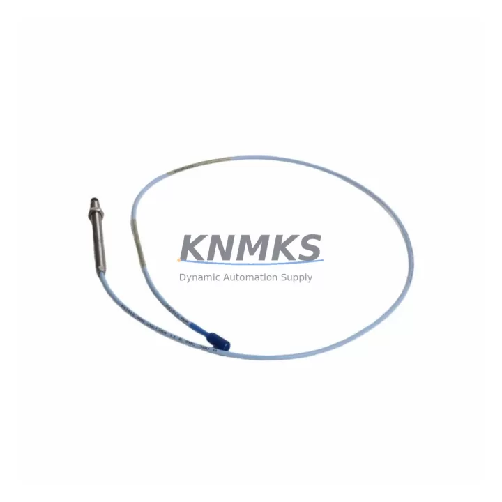
Bently Nevada 330103-13-20-10-02-00 Migration-Ready Proximity Transducer for Legacy Control Systems
The Bently Nevada 330103-13-20-10-02-00 is an 8mm proximity transducer engineered for the 3300 XL Series vibration monitoring platform. As aging distributed control systems and condition monitoring networks reach end-of-life, this unit serves as a direct migration-ready replacement for facilities managing legacy rotating machinery protection systems. Whether you are executing a planned retrofit of a turbine monitoring cabinet, replacing a discontinued sensor in a compressor train, or restoring a critical vibration channel after an unplanned failure, the 330103-13-20-10-02-00 delivers the dimensional accuracy, output linearity, and signal integrity required for seamless integration into existing Bently Nevada architectures.
Before committing to a replacement order, engineers should verify several key parameters against the existing installation. The transducer operates on the standard Bently Nevada proximitor voltage supply, typically –24 VDC, and the field wiring must be confirmed for correct polarity and shielding continuity back to the proximitor enclosure. Terminal block assignments at the junction box and at the monitor rack input card — commonly a 3300/16 or 3300/20 series I/O module — should be cross-referenced against the original loop drawing to avoid signal inversion or ground loop issues. The 330103-13-20-10-02-00 uses a 5-metre integral cable with a standard Bently Nevada connector, so installers must confirm that the existing cable tray routing and connector interface at the proximitor match this configuration before installation.
Backplane and rack compatibility is equally important. In systems where the 3300 XL monitor rack is populated alongside a 3500/42M Proximitor/Seismic Monitor or a 3500/22M Transient Data Interface, the transducer gap voltage and scale factor must be re-entered or verified in the rack configuration software after replacement. If the control system communicates over a Modbus RTU or FOUNDATION Fieldbus segment, the monitor channel address and tag mapping in the DCS historian should be confirmed unchanged after the swap to prevent data discontinuity in the process control narrative.
For facilities upgrading from older 7200 Series or 3300 NSv transducer assemblies to the current 3300 XL platform, the 330103-13-20-10-02-00 represents a validated migration path. The physical thread form (M8 × 1.0), mounting bracket footprint, and proximitor driver compatibility have been maintained across generations, which significantly reduces mechanical rework during a panel upgrade. However, installers should confirm that the target proximitor — such as a 330180 or 330130 series driver — is rated for the cable length and target material combination present in the field. Gap setting procedures using a digital voltmeter should be performed at commissioning to confirm the –10 VDC nominal gap output within the linear range of the transducer system.
In control cabinet upgrade projects where space is constrained, the compact form factor of the 330103-13-20-10-02-00 allows it to be installed in the same footprint as the legacy unit without requiring panel cutout modifications. When the retrofit also involves replacing the associated 3300 XL rack power supply or adding a 3500/15 Power Supply module to support expanded I/O, the transducer installation can proceed in parallel with the electrical work, reducing total outage duration. Facilities that are simultaneously migrating their HMI from an older Wonderware or iFIX-based system to a modern SCADA platform should ensure that the vibration channel tag names and engineering unit scaling are preserved in the new display configuration to avoid operator confusion during the transition period.
All units supplied by KNMKS are tested prior to shipment to verify output voltage linearity, cable continuity, and connector integrity. Stock is maintained to support urgent breakdown replacement scenarios, and orders are processed with priority dispatch to minimise machine downtime. Each 330103-13-20-10-02-00 is covered by a support terms confirmed by quotation against manufacturing defects, providing procurement teams with the assurance needed for long-term spare parts planning in critical rotating equipment applications.
Migration Compatibility Table
| Parameter | Detail |
|---|---|
| SKU / Part Number | 330103-13-20-10-02-00 |
| Brand / Series | Bently Nevada 3300 XL |
| Sensor Type | 8mm Eddy-Current Proximity Transducer |
| Cable Length | 5 metres (integral) |
| Thread Form | M8 × 1.0 |
| Supply Voltage | –24 VDC (via proximitor driver) |
| Output (Nominal Gap) | –10 VDC ± 0.5 VDC |
| Compatible Proximitors | 330180, 330130 series |
| Compatible Monitor Racks | 3300/16, 3300/20, 3500/42M |
| Legacy Replacement Path | 7200 Series, 3300 NSv transducers |
| Communication Compatibility | Modbus RTU, FOUNDATION Fieldbus (via monitor rack) |
| Installation Space | Same footprint as legacy 3300 XL units — no panel modification required |
| Commissioning Requirement | Gap voltage verification at –10 VDC nominal; scale factor confirmation in rack software |
| Pre-Shipment Testing | Output linearity, cable continuity, connector integrity |
| Support terms | 12 months against manufacturing defects |
| Country of Origin | USA |
Retrofit Planning for Existing Automation Systems
A successful retrofit begins well before the maintenance window opens. When planning the replacement of a 330103-13-20-10-02-00 in an operating plant, the engineering team should pull the existing loop drawings and confirm the wiring scheme at both the field junction box and the 3300 XL monitor rack terminal strip. In racks that also house a 3500/20 Rack Interface Module for system-level communication, the channel configuration file should be backed up before any hardware is disturbed. If the plant is running a 3500/15 Power Supply in a redundant configuration, the power feed to the affected monitor channel should be isolated on the standby supply before the transducer is disconnected, preserving monitoring continuity on adjacent channels.
For installations where the transducer feeds into a 3300/20 I/O module that also aggregates signals from a 330130 proximitor driver and a 3300 XL Keyphasor module, the replacement sequence should be coordinated so that the Keyphasor reference signal remains active throughout the swap. This prevents the vibration monitor from generating spurious trip signals during the transducer exchange. Where the control system includes a 3500/22M Transient Data Interface capturing waveform data for machinery diagnostics, the data acquisition should be paused and restarted after the new transducer is gapped and verified to ensure clean baseline data in the historian.
In cabinet upgrade projects that involve replacing the entire 3300 XL rack with a 3500 Series frame, the 330103-13-20-10-02-00 transducer and its associated 330180 proximitor can be reused without modification, as the 3500 platform accepts the same transducer system. This significantly reduces the bill of materials for the upgrade and allows the field wiring to remain undisturbed. Signal isolators may be required at the rack output if the new DCS input card has different impedance characteristics than the original system.
Downtime Control During System Migration
Minimising unplanned downtime during a transducer replacement requires a structured approach to pre-staging, execution, and verification. Before the maintenance window, the replacement 330103-13-20-10-02-00 should be bench-tested using a portable proximitor and a steel target to confirm output voltage at the specified gap distance. This eliminates the risk of installing a non-conforming unit and discovering the fault only after the machine is returned to service.
During the replacement, the original program logic in the associated safety system or DCS controller should not be modified. The transducer swap is a hardware-only operation, and any changes to the monitor rack configuration — such as adjusting the danger or alert setpoints — should be deferred to a separate management-of-change process. If the plant uses a Bently Nevada System 1 software platform for online machinery management, the channel should be placed in bypass mode before the transducer is removed and returned to active monitoring only after the gap voltage has been confirmed within specification.
Post-installation verification should include a full channel functional test: confirm the proximitor output voltage at the monitor rack terminal, verify the channel reading in the DCS or historian, and check that no active alarms are present on the affected machine train. Where the HMI displays a vibration trend for the replaced channel, the operator should confirm that the trend is updating correctly and that the engineering units and tag description match the pre-outage configuration. Documenting the as-found and as-left gap voltages in the maintenance management system provides a traceable record for future reliability reviews.
Retrofit Support FAQ
Q: Is the 330103-13-20-10-02-00 a direct drop-in replacement for older 3300 NSv and 7200 Series proximity transducers?
A: In most cases, yes. The thread form, mounting bracket dimensions, and proximitor driver compatibility are consistent across the 3300 XL platform. However, the cable length and connector type should be verified against the existing installation before ordering, as some legacy installations used extension cables or custom connector assemblies that may require adapters.
Q: What commissioning steps are required after installing the replacement transducer?
A: The primary commissioning step is gap setting — adjust the transducer-to-target gap until the proximitor output reads –10 VDC ± 0.5 VDC using a calibrated digital voltmeter. After gapping, confirm the channel reading at the monitor rack and in the DCS historian. If the rack uses a configuration file (as with 3500 Series monitors), verify that the scale factor and transducer type settings match the 330103-13-20-10-02-00 specification.
Q: Can the existing field wiring be reused when replacing the transducer?
A: Yes, provided the wiring is in good condition and the cable shielding is intact. The 330103-13-20-10-02-00 uses the standard Bently Nevada two-conductor shielded cable interface. Inspect the junction box terminals for corrosion and confirm that the shield drain wire is grounded at one end only (typically at the proximitor enclosure) to avoid ground loops.
Q: What support terms and supply assurance does KNMKS provide for this part?
A: Every 330103-13-20-10-02-00 supplied by KNMKS carries a support terms confirmed by quotation against manufacturing defects from the date of shipment. Units are pre-tested before dispatch to verify electrical performance. We maintain stock to support both planned maintenance schedules and emergency breakdown replacements, with priority processing available for critical plant situations. Contact admin@knmks.com or +86 18359268345 for availability and lead time confirmation.
© 2026 KNMKS. All rights reserved.
Original Source: https://knmks.com
Contact: admin@knmks.com | +86 18359268345
Product Identification
- Brand / Ecosystem
-
Bently Nevada
Bently Nevada - Model / Series
-
330103-13-20-10-02-00
Bently Nevada 3300 XL / 3301 Series - Product Family
- Sensors
- Availability Status
- Available on request after model and quantity confirmation
- Inquiry Type
- B2B RFQ, replacement inquiry and project spare-part request
- Pre-Quote Check
- Exact SKU, brand, series, quantity, nameplate photos and destination country are checked before quotation
System Path
Where this product fits in the KNMKS automation structure.
Specification & Inquiry Focus
- Sensor range
- Photoelectric, proximity and process sensors
- Common needs
- Output type, distance and connector
- Project support
- Machine detection and replacement inquiry
Buyer Confirmation
Information KNMKS checks before replying.
- Exact model
- 330103-13-20-10-02-00
- Brand / ecosystem
- Bently Nevada
- Product family
- Sensors
- Application note
- Replacement, maintenance, project build or spare-part list
- Useful photos
- Nameplate, installed unit, cabinet layout or connector side
- Delivery details
- Quantity, destination country and target schedule
Document Support
Files and notes can be confirmed during quotation.
- Product photos or nameplate confirmation when available
- Packing and delivery notes before quotation confirmation
- Support scope and delivery terms confirmed per inquiry
- Export document coordination for qualified B2B requests
Inquiry Support
- NPN/PNP, analog and digital output checking
- Connector and cable compatibility review
- Fast inquiry support for maintenance teams
What to Send Us
- Brand and exact model number: Bently Nevada 330103-13-20-10-02-00
- Quantity and required delivery time
- Application, replacement requirement or nameplate photo
- Destination country and shipping preference
RFQ Preparation
This is a product inquiry page built for RFQ communication.
Fast Model Check
Send this model to KNMKS for confirmation.
Include quantity, destination country and photos if this is a maintenance replacement. The inquiry will be saved with a reference number after submission.
Brand & Compatibility Note
KNMKS displays automation product information for well-known industrial brand ecosystems and compatible replacement references. Brand names are used for product identification and compatibility reference only; final availability and commercial terms are confirmed per quotation.
 Manufacturing
 Machine Tools
 Packaging
 Energy & Power



 PLCs & Controllers
 HMI & Displays
 Servo Systems
 Variable Frequency Drives