
Overview
Bently Nevada 330103-09-18-10-02-00 Migration-Ready Proximity Transducer: Legacy System Retrofit & Compatibility Upgrade
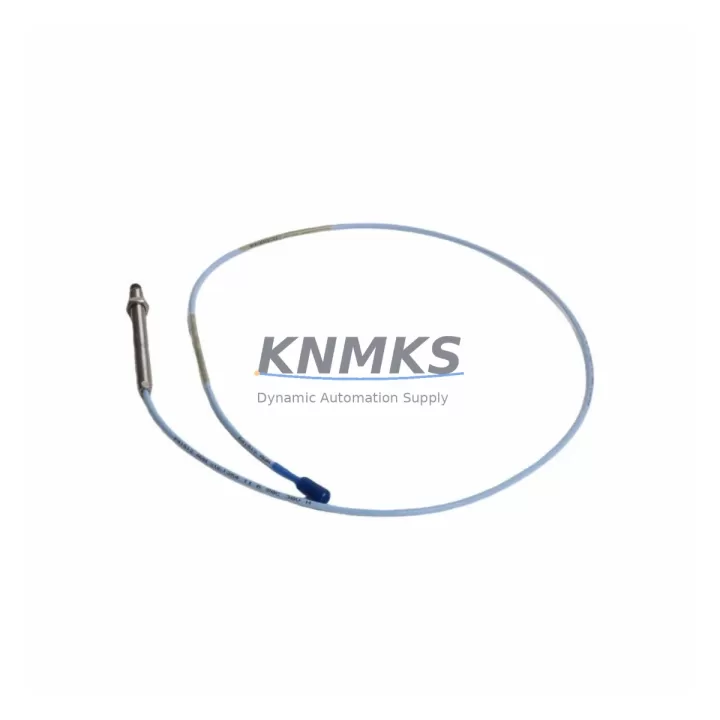
The Bently Nevada 330103-09-18-10-02-00 is an 8mm proximity transducer engineered for seamless integration into existing 3300 XL Series vibration monitoring systems. As industrial facilities face the growing challenge of maintaining aging machinery protection infrastructure, this transducer serves as a verified drop-in replacement for discontinued proximity probe assemblies across a wide range of rotating equipment applications — including steam turbines, gas compressors, centrifugal pumps, and gearboxes. Whether you are executing a planned control system upgrade, responding to an emergency spare parts shortage, or modernizing a legacy monitoring loop, the 330103-09-18-10-02-00 delivers the electrical and mechanical compatibility required to restore full system functionality with minimal disruption to production.
Before committing to a retrofit, engineers must confirm several critical parameters. Power supply compatibility is the first checkpoint: the 330103-09-18-10-02-00 operates on a standard -24 VDC bias voltage supplied through the Bently Nevada 3300 XL proximitor/seismic transducer, and the existing field wiring must be verified to carry the correct supply without voltage drop across long cable runs. Terminal wiring at the junction box and at the monitor input card — typically a 3300/16 or 3300/20 series I/O module — should be inspected for correct polarity and shielding continuity before the new transducer is energized. The coaxial cable assembly, including the extension cable and proximitor, must be matched to the correct gap voltage range to ensure the output sensitivity of 7.87 V/mm (200 mV/mil) is maintained within the monitor’s acceptance window.
Backplane interface and module addressing are equally important during migration. If the replacement is being performed within a rack-mounted 3500 Series machinery protection system — a common upgrade path from older 3300 XL installations — the slot address, channel configuration, and transducer type selection within the System 1 Evolution software must be updated to reflect the new probe assembly. Failure to update the transducer type in the configuration database will result in incorrect gap, direct, and 1X/2X vector readings, potentially triggering nuisance trips or masking genuine machinery faults.
Program logic compatibility should also be reviewed when the transducer replacement is part of a broader DCS or safety system migration. If the vibration monitor outputs are wired into a Rockwell Automation ControlLogix or Allen-Bradley PLC rack via analog input modules, the 4–20 mA or relay output scaling must be re-verified after the transducer swap. Similarly, HMI faceplate displays configured in FactoryTalk View or Wonderware InTouch that reference vibration trend tags should be checked to confirm engineering unit scaling has not shifted. Communication links between the 3500 rack and the plant historian via Modbus RTU or OPC-DA should be tested under live conditions before the system is returned to automatic protection mode.
Installation space confirmation is a practical concern that is often overlooked during the planning phase. The 330103-09-18-10-02-00 uses a standard 8mm probe tip diameter with a 5/16-28 UNF thread, and the available clearance in the bearing housing probe port must be measured to confirm the probe body and locknut can be installed without interference from adjacent pipework or insulation cladding. Firmware version compatibility between the proximitor and the monitor card should be confirmed with the Bently Nevada product compatibility matrix, particularly if the monitor firmware has been updated since the original system commissioning.
Migration Compatibility Table
| Parameter | 330103-09-18-10-02-00 Specification | Retrofit / Migration Note |
|---|---|---|
| Probe Diameter | 8mm | Verify bearing housing port thread: 5/16-28 UNF |
| Cable Length | 9m (probe) + 9m (extension) | Match total cable length to proximitor calibration range |
| Output Sensitivity | 7.87 V/mm (200 mV/mil) | Confirm monitor input card accepts this sensitivity |
| Bias Voltage | -24 VDC nominal | Verify field wiring voltage drop; check terminal polarity |
| Compatible Monitor | 3300 XL, 3500 Series | Update transducer type in System 1 configuration if migrating to 3500 |
| Communication Protocol | Analog / Relay output; Modbus RTU via 3500 rack | Test OPC-DA / Modbus link after replacement |
| Installation Thread | 5/16-28 UNF | Confirm probe port clearance; check locknut torque spec |
| Firmware Compatibility | Per Bently Nevada compatibility matrix | Verify monitor card firmware version before energizing |
| Replacement Scope | Drop-in for discontinued 330103 series probes | No mechanical modification required for same-series swap |
| Support terms | 12 Months | Covers manufacturing defects; includes pre-shipment functional test |
Retrofit Planning for Existing Automation Systems
A successful retrofit of the 330103-09-18-10-02-00 into an operating plant environment requires a structured bill-of-materials review that goes beyond the probe itself. In most 3300 XL installations, the probe is paired with a Bently Nevada 330130 proximitor (the signal conditioning module mounted in the field junction box), and both components must be replaced as a matched set if the proximitor has exceeded its service life or if its calibration certificate has lapsed. The coaxial extension cable — typically a Bently Nevada 330854 or 330855 series armored cable — must also be inspected for jacket damage, connector corrosion, and shield continuity, as a degraded cable will introduce noise into the gap voltage signal and cause erratic vibration readings even with a new probe installed.
At the monitor rack level, the 3300/16 or 3300/20 dual-channel monitor cards that receive the transducer signal should be checked for alarm setpoint configuration and OK relay wiring before the new probe is commissioned. If the site is migrating from a 3300 XL rack to a 3500/42M six-channel monitor as part of a broader machinery protection upgrade, the I/O terminal block wiring must be re-mapped to the new channel assignments, and the 3500 rack’s power supply module — such as the 3500/15 power supply — must be confirmed to have sufficient capacity to support the additional transducer load. Signal isolators or Zener barriers installed in the intrinsically safe version of the loop (the -02-00 suffix in the SKU indicates the IS-rated configuration) must be verified to be compatible with the new probe’s electrical parameters.
For sites running a hybrid control architecture where the 3500 rack communicates with a Rockwell Automation ControlLogix PLC via a 3500/92 communication gateway, the gateway’s Modbus register map should be exported and archived before the replacement begins. This ensures that if the replacement process requires a rack power cycle, the PLC program’s vibration interlock logic can be verified against the restored register values without relying on memory. Programming cables and laptops loaded with System 1 Evolution and the 3500 Rack Configuration Utility should be staged at the control room before the maintenance window opens.
Downtime Control During System Migration
Minimizing unplanned downtime during a proximity transducer replacement requires a pre-approved maintenance procedure that sequences the work to protect the original program logic and maintain field control continuity. The recommended approach is to place the affected monitor channel into bypass mode within the System 1 software before disconnecting the field wiring, which prevents the OK relay from de-energizing and triggering a spurious machinery trip during the probe swap. The bypass status should be logged in the plant’s permit-to-work system with a defined time limit to ensure the channel is not left in bypass indefinitely.
Once the new 330103-09-18-10-02-00 probe is installed and the coaxial cable connections are torqued to specification, the gap voltage should be measured at the proximitor output terminals using a calibrated digital multimeter before the monitor channel is taken out of bypass. The gap voltage should fall within the linear range specified in the Bently Nevada calibration chart for the target gap distance — typically between -10 VDC and -18 VDC for an 8mm probe at the recommended 1.0 mm (40 mil) installation gap. Only after the gap voltage is confirmed within range should the channel bypass be removed and the OK relay state verified.
All pre-replacement and post-replacement vibration readings — including direct (overall) amplitude, 1X and 2X vector components, and DC gap voltage — should be documented and compared against the baseline values recorded during the previous calibration or machinery survey. Any deviation greater than 10% from the baseline should be investigated before the machine is returned to service. This documentation also supports the support terms confirmed by quotation claim process in the event that a manufacturing defect is identified during the confirmed support period. Pre-shipment functional testing performed at our facility ensures that each unit shipped meets the original Bently Nevada specification, reducing the risk of commissioning failures and shortening the overall maintenance window.
Retrofit Support FAQ
Q1: Is the 330103-09-18-10-02-00 a direct replacement for the original Bently Nevada 330103 series probes?
Yes. The 330103-09-18-10-02-00 is a verified drop-in replacement for the original Bently Nevada 330103 series 8mm proximity probe assemblies used in 3300 XL machinery protection systems. No mechanical modification to the bearing housing probe port is required for a same-series swap. The SKU suffix (-09-18-10-02-00) encodes the probe length, cable length, connector type, and IS rating, so confirm that your existing installation matches these parameters before ordering.
Q2: What commissioning steps are required after installation?
After mechanical installation, measure the gap voltage at the proximitor output terminals with the machine stationary. Adjust the probe gap to achieve the target gap voltage per the Bently Nevada calibration chart. Remove the monitor channel bypass, verify the OK relay energizes, and confirm that direct vibration amplitude and 1X vector readings are consistent with the pre-replacement baseline. Update the System 1 configuration database if the replacement is part of a migration to a 3500 Series rack.
Q3: Can I use this transducer with a 3500 Series monitor if I am migrating from a 3300 XL system?
Yes, the 330103-09-18-10-02-00 is compatible with the Bently Nevada 3500 Series machinery protection system when used with the appropriate 3500/42M or 3500/40M monitor card. You must update the transducer type selection in the 3500 Rack Configuration Utility and verify that the I/O terminal block wiring matches the new channel assignments. The 3500/15 power supply capacity should also be confirmed to support the additional transducer load.
Q4: What does the support terms confirmed by quotation cover, and how is inventory availability managed?
The support terms confirmed by quotation cover manufacturing defects in materials and workmanship from the date of shipment. Each unit undergoes a pre-shipment functional test to verify gap voltage output, sensitivity, and connector integrity before dispatch. We maintain dedicated inventory of the 330103-09-18-10-02-00 and related 3300 XL series components to support emergency spare parts requirements and planned maintenance schedules. Contact our sales team for lead time confirmation and volume pricing for multi-unit retrofit projects.
© 2026 KNMKS. All rights reserved.
Original Source: https://knmks.com
Contact: admin@knmks.com | +86 18359268345
Product Identification
- Brand / Ecosystem
-
Bently Nevada
Bently Nevada - Model / Series
-
330103-09-18-10-02-00
Bently Nevada 3300 XL / 3301 Series - Product Family
- Sensors
- Availability Status
- Available on request after model and quantity confirmation
- Inquiry Type
- B2B RFQ, replacement inquiry and project spare-part request
- Pre-Quote Check
- Exact SKU, brand, series, quantity, nameplate photos and destination country are checked before quotation
System Path
Where this product fits in the KNMKS automation structure.
Specification & Inquiry Focus
- Sensor range
- Photoelectric, proximity and process sensors
- Common needs
- Output type, distance and connector
- Project support
- Machine detection and replacement inquiry
Buyer Confirmation
Information KNMKS checks before replying.
- Exact model
- 330103-09-18-10-02-00
- Brand / ecosystem
- Bently Nevada
- Product family
- Sensors
- Application note
- Replacement, maintenance, project build or spare-part list
- Useful photos
- Nameplate, installed unit, cabinet layout or connector side
- Delivery details
- Quantity, destination country and target schedule
Document Support
Files and notes can be confirmed during quotation.
- Product photos or nameplate confirmation when available
- Packing and delivery notes before quotation confirmation
- Support scope and delivery terms confirmed per inquiry
- Export document coordination for qualified B2B requests
Inquiry Support
- NPN/PNP, analog and digital output checking
- Connector and cable compatibility review
- Fast inquiry support for maintenance teams
What to Send Us
- Brand and exact model number: Bently Nevada 330103-09-18-10-02-00
- Quantity and required delivery time
- Application, replacement requirement or nameplate photo
- Destination country and shipping preference
RFQ Preparation
This is a product inquiry page built for RFQ communication.
Fast Model Check
Send this model to KNMKS for confirmation.
Include quantity, destination country and photos if this is a maintenance replacement. The inquiry will be saved with a reference number after submission.
Brand & Compatibility Note
KNMKS displays automation product information for well-known industrial brand ecosystems and compatible replacement references. Brand names are used for product identification and compatibility reference only; final availability and commercial terms are confirmed per quotation.
 Manufacturing
 Machine Tools
 Packaging
 Energy & Power



 PLCs & Controllers
 HMI & Displays
 Servo Systems
 Variable Frequency Drives