
Overview
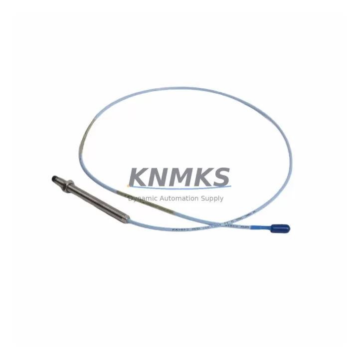
Bently Nevada 330103-04-13-10-02-CN 3300 XL Migration-Ready Proximity Transducer for Legacy Control Systems
The Bently Nevada 330103-04-13-10-02-CN is an 8mm eddy-current proximity transducer from the 3300 XL series, engineered for continuous vibration and position monitoring in rotating machinery. As legacy Bently Nevada 3300 series installations reach end-of-support milestones, plant engineers and reliability teams are increasingly sourcing verified replacement units to sustain critical monitoring loops without triggering full system overhauls. This unit is stocked, tested, and ready to ship as a migration-ready drop-in replacement for existing 3300 XL transducer assemblies.
Whether you are maintaining a turbine protection system, compressor train, or pump monitoring rack, the 330103-04-13-10-02-CN delivers the same output sensitivity, gap voltage range, and cable length specification as the original factory configuration. Each unit undergoes pre-shipment functional verification to confirm signal linearity, insulation integrity, and connector continuity before dispatch.
Migration Compatibility Table
| Parameter | Specification / Recommendation |
|---|---|
| Replaced / Superseded Model | Bently Nevada 330103-04-13-10-02-CN (3300 XL Series) |
| Transducer Type | 8mm Eddy-Current Proximity Transducer |
| Compatible Driver / Proximitor | Bently Nevada 3300 XL Proximitor (e.g., 330180 series) |
| Output Sensitivity | 7.87 V/mm (200 mV/mil) — verify against existing loop calibration |
| Cable Length | Confirm extension cable length matches original installation (standard: 5m / 9m) |
| Connector Interface | Standard BNC / coaxial — inspect mating connector on extension cable for wear |
| Mounting Thread | M10 × 1 — verify bracket thread condition before installation |
| Gap Voltage (Operating Range) | −10 VDC to −18 VDC — set gap to −12 VDC nominal during commissioning |
| Power Supply Requirement | −24 VDC (supplied via Proximitor) — confirm rack PSU capacity before swap |
| Communication / Signal Type | Analog voltage output — no protocol migration required |
| Installation Space | Confirm probe tip clearance and bracket reach match original geometry |
| Firmware / Software Dependency | None for transducer; verify System 1 or TDXnet configuration if monitor is also replaced |
| Replacement Recommendation | Direct drop-in; replace extension cable and Proximitor if corrosion or drift is detected |
| Commissioning Focus | Gap setting, signal polarity, alarm setpoint verification, trend baseline reset |
| Support terms | support terms confirmed by quotation — covers manufacturing defects and functional failure under normal operating conditions |
Retrofit Planning for Existing Automation Systems
Replacing the 330103-04-13-10-02-CN within an active machinery protection system requires a structured approach that accounts for the full transducer chain. The proximity transducer does not operate in isolation — it functions as part of a three-component system alongside the extension cable (typically a 330130 series extension cable) and the Proximitor sensor (commonly the 330180-51-00 or equivalent 3300 XL Proximitor). Before initiating the swap, engineers should inspect all three components for signal drift, insulation breakdown, or connector oxidation, as replacing only the transducer while retaining a degraded extension cable or Proximitor will not restore system accuracy.
At the rack level, the 3300 XL monitor cards — such as the 3300/16 dual-channel monitor or the 3300/20 four-channel monitor — must be verified for channel configuration and alarm setpoint integrity. If the monitor card has been in service for an extended period, this is an appropriate time to audit the rack’s power supply module capacity, particularly if additional I/O expansion or a new communication gateway has been added to the same cabinet. Overloaded rack power supplies are a common but overlooked cause of signal instability after transducer replacement.
For plants running Bently Nevada System 1 software or interfacing via a 3500/92 communication gateway, the transducer replacement itself does not require software reconfiguration — the channel parameters remain valid as long as the replacement unit matches the original sensitivity and cable length. However, if the replacement is part of a broader migration from the 3300 series to the 3500 series platform, engineers will need to remap channel addresses, update System 1 database entries, and re-establish communication links to the DCS or SCADA layer. In such cases, coordinating the transducer swap with the monitor card upgrade and the HMI screen update in a single planned outage window is strongly recommended to minimize total downtime exposure.
Where the existing control cabinet includes signal isolators or barriers between the Proximitor output and the DCS analog input card, verify that the isolator’s input impedance and voltage range remain compatible with the replacement transducer’s output characteristics. Mismatched isolator specifications are a frequent source of post-replacement calibration errors that are difficult to diagnose without systematic loop testing.
Downtime Control During System Migration
Minimizing unplanned downtime during a proximity transducer replacement begins with pre-staging all replacement components before the maintenance window opens. For the 330103-04-13-10-02-CN, this means having the replacement transducer, the correct extension cable, and a verified Proximitor unit on-site and bench-tested before the machine is taken offline. Attempting to source components during an active outage significantly extends downtime and increases the risk of installation errors under time pressure.
Prior to disconnecting the existing transducer, record the current gap voltage reading and the vibration trend baseline from the monitor display or System 1 historian. These reference values are essential for verifying that the replacement unit has been correctly gapped and that the signal output is within the expected operating range before the machine is returned to service. If the monitor card supports channel bypass or inhibit mode, activate it during the swap to prevent spurious trips from propagating to the turbine control system or emergency shutdown logic.
After installation, the commissioning sequence should follow the standard Bently Nevada gap-setting procedure: power the Proximitor, measure the DC gap voltage at the monitor terminal, adjust the transducer axial position until the gap voltage reaches the nominal −12 VDC target, and lock the mounting hardware. Confirm that the vibration signal is present and noise-free at low shaft speed before releasing the inhibit and returning the channel to normal protection mode. Document the as-left gap voltage, sensitivity verification result, and alarm setpoint confirmation in the maintenance record to support future audits and support requests.
For sites where continuous operation is required and a hot-swap is being considered, consult the machine OEM and the Bently Nevada installation manual before proceeding — proximity transducer replacement on live rotating equipment carries significant safety risk and is not recommended without explicit OEM authorization and appropriate personnel protection measures in place.
Retrofit Support FAQ
Q1: Is the 330103-04-13-10-02-CN a direct replacement for other 3300 XL 8mm transducers?
The 330103-04-13-10-02-CN is a specific configuration within the 3300 XL 8mm transducer family. The suffix digits encode cable length, connector type, and temperature rating. Before substituting a different suffix variant, confirm that the cable length, operating temperature range, and connector configuration match your installation requirements. When in doubt, contact our technical team with your existing part number and installation drawing for a verified cross-reference.
Q2: What commissioning steps are required after installation?
After mechanical installation, the primary commissioning steps are: (1) set the transducer gap to achieve the nominal −12 VDC output at the Proximitor, (2) verify signal sensitivity against the monitor channel configuration, (3) confirm alarm and danger setpoints are active and correctly scaled, and (4) reset the vibration trend baseline in System 1 or the local monitor display. A full loop calibration check is recommended if the extension cable or Proximitor was also replaced.
Q3: Does the unit ship with a test report, and what does the support terms confirmed by quotation cover?
Yes. Each 330103-04-13-10-02-CN unit is functionally tested prior to shipment. The support terms confirmed by quotation cover manufacturing defects and functional failure under normal operating conditions as defined in the Bently Nevada installation specification. The support terms does not cover damage resulting from incorrect installation, overvoltage, mechanical impact, or operation outside the specified environmental limits. Support requests are supported with the original invoice and installation documentation.
Q4: What is the typical lead time and inventory availability?
This unit is maintained availability confirmed by RFQ for immediate dispatch. Standard lead time is 3–7 business days for international shipments, subject to customs clearance. For urgent requirements or bulk orders supporting a planned outage, contact admin@knmks.com or call +86 18359268345 to confirm current stock levels and arrange priority shipping.
© 2026 KNMKS. All rights reserved.
Original Source: https://knmks.com
Contact: admin@knmks.com | +86 18359268345
Product Identification
- Brand / Ecosystem
-
Bently Nevada
Bently Nevada - Model / Series
-
330103-04-13-10-02-CN
Bently Nevada 3300 XL / 3301 Series - Product Family
- Sensors
- Availability Status
- Available on request after model and quantity confirmation
- Inquiry Type
- B2B RFQ, replacement inquiry and project spare-part request
- Pre-Quote Check
- Exact SKU, brand, series, quantity, nameplate photos and destination country are checked before quotation
System Path
Where this product fits in the KNMKS automation structure.
Specification & Inquiry Focus
- Sensor range
- Photoelectric, proximity and process sensors
- Common needs
- Output type, distance and connector
- Project support
- Machine detection and replacement inquiry
Buyer Confirmation
Information KNMKS checks before replying.
- Exact model
- 330103-04-13-10-02-CN
- Brand / ecosystem
- Bently Nevada
- Product family
- Sensors
- Application note
- Replacement, maintenance, project build or spare-part list
- Useful photos
- Nameplate, installed unit, cabinet layout or connector side
- Delivery details
- Quantity, destination country and target schedule
Document Support
Files and notes can be confirmed during quotation.
- Product photos or nameplate confirmation when available
- Packing and delivery notes before quotation confirmation
- Support scope and delivery terms confirmed per inquiry
- Export document coordination for qualified B2B requests
Inquiry Support
- NPN/PNP, analog and digital output checking
- Connector and cable compatibility review
- Fast inquiry support for maintenance teams
What to Send Us
- Brand and exact model number: Bently Nevada 330103-04-13-10-02-CN
- Quantity and required delivery time
- Application, replacement requirement or nameplate photo
- Destination country and shipping preference
RFQ Preparation
This is a product inquiry page built for RFQ communication.
Fast Model Check
Send this model to KNMKS for confirmation.
Include quantity, destination country and photos if this is a maintenance replacement. The inquiry will be saved with a reference number after submission.
Brand & Compatibility Note
KNMKS displays automation product information for well-known industrial brand ecosystems and compatible replacement references. Brand names are used for product identification and compatibility reference only; final availability and commercial terms are confirmed per quotation.
 Manufacturing
 Machine Tools
 Packaging
 Energy & Power



 PLCs & Controllers
 HMI & Displays
 Servo Systems
 Variable Frequency Drives