
Overview
Bently Nevada 330103-03-15-10-02-00 Maintenance-Proven Spare Part for Factory Uptime
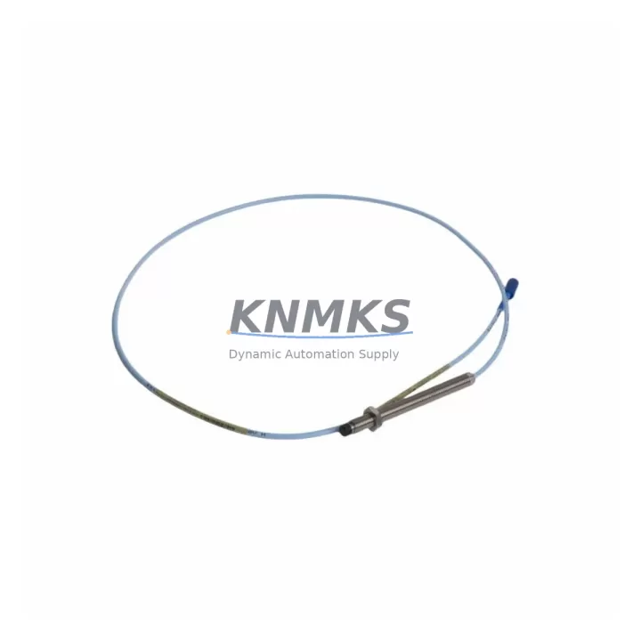
The Bently Nevada 330103-03-15-10-02-00 is an 8mm proximity transducer designed for continuous shaft vibration and position monitoring within the 3300 XL Series condition monitoring system. As a maintenance-proven spare part, it is engineered to deliver reliable radial vibration measurement in rotating machinery applications including turbines, compressors, pumps, and motors across oil & gas, power generation, petrochemical, and heavy manufacturing facilities. Sourced as an original replacement component, this transducer supports uninterrupted factory uptime by enabling rapid field swap-out with zero system reconfiguration when paired with the correct extension cable and proximitor.
For maintenance engineers managing critical rotating assets, having the 330103-03-15-10-02-00 in the spare parts cabinet is a fundamental risk mitigation strategy. Proximity transducer failures are among the leading causes of unplanned machinery shutdowns. A verified, pre-tested replacement on the shelf reduces mean time to repair (MTTR) from days to hours, protecting production continuity and avoiding costly emergency procurement.
Spare Maintenance Table
| Parameter | Specification |
|---|---|
| SKU / Part Number | 330103-03-15-10-02-00 |
| Brand | Bently Nevada |
| Series | 3300 XL Proximity Transducer System |
| Probe Diameter | 8 mm |
| Cable Length | 1.5 m (integral cable) |
| Extension Cable Compatibility | 3300 XL Series Extension Cable (e.g. 330130-045-00-00) |
| Proximitor / Driver Compatibility | 3300 XL 8mm Proximitor (e.g. 330180-X1-05) |
| Measurement Type | Radial Vibration, Axial Position, Speed |
| Output Signal | -18 VDC nominal (standard Bently Nevada output) |
| Gap Voltage Range | -10 VDC to -18 VDC |
| Sensitivity | 200 mV/mil (7.87 V/mm) |
| Linear Range | 0.25 mm to 2.26 mm (10 mil to 89 mil) |
| Operating Temperature | -35°C to +177°C (probe tip) |
| Target Material | Steel / Stainless Steel (AISI 4140 recommended) |
| Installation Environment | Industrial — turbines, compressors, pumps, motors |
| Approvals | CE, ATEX, FM (refer to original datasheet) |
| Origin | USA |
| Support terms | 12 Months |
| Condition | New / Original Replacement |
| Testing | Functionally tested before shipment |
Maintenance Planning for Continuous Operation
When a 330103-03-15-10-02-00 proximity transducer is flagged during routine vibration monitoring or point inspection, the replacement process should be treated as a system-level maintenance event rather than a single-component swap. Experienced maintenance engineers know that a transducer fault can originate from the probe itself, the extension cable, the proximitor driver, or the signal conditioning chain — and each element must be evaluated before returning the loop to service.
Begin by inspecting the 3300 XL Extension Cable (such as the 330130-045-00-00 or equivalent length variant) for jacket damage, connector corrosion, or continuity loss. Extension cables routed through conduit near high-vibration zones are particularly susceptible to fatigue cracking at the connector ends. A damaged cable will produce erratic gap voltage readings that mimic a failed transducer, leading to unnecessary probe replacement.
Next, verify the 3300 XL 8mm Proximitor / Driver Module (e.g., 330180-X1-05) output voltage and bias level using a calibrated multimeter. A proximitor with degraded oscillator performance will fail to drive the transducer to its correct linear range, producing false high-vibration alarms. If the proximitor is more than 8–10 years old or has been exposed to moisture ingress, proactive replacement alongside the transducer is strongly recommended.
Within the control cabinet, inspect the 3500 Series Rack or equivalent monitoring rack input card for correct channel configuration, alarm setpoints, and OK relay status. Confirm that the 3500/42M Proximitor I/O Module or equivalent I/O card is seated correctly and that terminal block connections are tight and free of oxidation. Loose terminations at the I/O module are a common source of intermittent vibration signal faults that are frequently misdiagnosed as transducer failures.
For facilities running integrated condition monitoring, also verify the communication module (such as a 3500/92 or equivalent Modbus/PROFIBUS gateway) is correctly forwarding vibration data to the DCS or SCADA historian. A transducer replacement that is not followed by a system communication check can leave the monitoring loop in a degraded state without triggering any visible alarm.
Finally, review the power supply module feeding the proximitor — typically a -24 VDC regulated supply. Voltage sag or ripple on the supply rail will directly affect transducer output accuracy. A dedicated power supply health check, including output voltage under load and ripple measurement, should be part of every proximity transducer replacement workflow.
Stocking one or two 330103-03-15-10-02-00 units alongside matched extension cables and a spare proximitor module creates a complete transducer loop spare kit — the most effective strategy for minimizing downtime on critical rotating machinery.
Site Replacement Workflow
Step 1 — Isolation and Lockout: Follow site LOTO procedures. Confirm the machinery is at rest and the monitoring channel is bypassed or acknowledged in the control system to prevent spurious shutdown trips during the replacement.
Step 2 — Gap Measurement and Documentation: Before removing the old transducer, record the installed gap distance (typically 1.0–1.5 mm for 8mm probes on steel targets). This reference value will be used to set the replacement probe to the correct initial gap, ensuring the output voltage falls within the -10 to -18 VDC linear range.
Step 3 — Transducer Removal: Disconnect the extension cable connector at the probe end. Unthread the transducer from the mounting bracket using the appropriate spanner. Inspect the mounting threads and bracket for wear or corrosion — replace the bracket if thread integrity is compromised.
Step 4 — New Transducer Installation: Install the 330103-03-15-10-02-00 replacement. Set the gap to the documented reference value using a feeler gauge or by monitoring the proximitor output voltage during adjustment. Torque the locknut to the manufacturer’s specification to prevent gap drift under vibration.
Step 5 — Cable Reconnection and Loop Verification: Reconnect the extension cable. Measure the proximitor output voltage at the terminal block to confirm correct gap and linear range. Verify the OK relay is energized and the monitoring system is displaying a valid vibration reading within expected baseline levels.
Step 6 — System Return to Service: Remove the bypass, clear the alarm acknowledgment, and confirm the channel is active in the monitoring rack. Document the replacement in the maintenance management system (CMMS) with the new probe serial number, installed gap, and output voltage for future reference.
This workflow is compatible with legacy 3300 Series installations being upgraded to 3300 XL components, supporting old system life extension without requiring full rack replacement.
Spare Parts Support FAQ
Q1: Is the 330103-03-15-10-02-00 a direct drop-in replacement for older 3300 Series proximity transducers?
The 330103-03-15-10-02-00 is a 3300 XL Series component. It is generally compatible with 3300 XL proximitor drivers and extension cables. For installations using legacy 3300 (non-XL) proximitors, compatibility should be verified against the proximitor model number and system documentation before installation. In most cases, upgrading the proximitor to a 3300 XL variant is recommended when replacing the transducer to ensure full system performance.
Q2: How should the 330103-03-15-10-02-00 be stored as a long-term spare?
Store in the original packaging or an ESD-safe, moisture-controlled environment at temperatures between -40°C and +85°C. Avoid storage near strong magnetic fields or corrosive atmospheres. Inspect the connector and cable jacket annually. Properly stored, proximity transducers maintain their calibration and performance characteristics for 5+ years without requiring recalibration before installation.
Q3: What testing is performed before shipment?
Each 330103-03-15-10-02-00 unit undergoes functional verification prior to shipment, including output voltage check, gap linearity confirmation, and connector integrity inspection. Units are shipped with protective end caps on the probe tip and connector to prevent transit damage. A support terms confirmed by quotation cover manufacturing defects and performance deviations from published specifications under normal operating conditions.
Q4: What is the lead time and long-term supply availability?
Stock units are available for immediate shipment. For procurement engineers managing annual maintenance budgets or multi-unit plant-wide spare programs, bulk order arrangements with reserved stock allocation are available. Long-term supply continuity is supported for facilities running extended asset life programs on 3300 XL-based monitoring systems. Contact our team to discuss consignment stock or scheduled delivery agreements tailored to your maintenance cycle.
© 2026 KNMKS. All rights reserved.
Original Source: https://knmks.com
Contact: admin@knmks.com | +86 18359268345
Product Identification
- Brand / Ecosystem
-
Bently Nevada
Bently Nevada - Model / Series
-
330103-03-15-10-02-00
Bently Nevada 3300 XL / 3301 Series - Product Family
- Sensors
- Availability Status
- Available on request after model and quantity confirmation
- Inquiry Type
- B2B RFQ, replacement inquiry and project spare-part request
- Pre-Quote Check
- Exact SKU, brand, series, quantity, nameplate photos and destination country are checked before quotation
System Path
Where this product fits in the KNMKS automation structure.
Specification & Inquiry Focus
- Sensor range
- Photoelectric, proximity and process sensors
- Common needs
- Output type, distance and connector
- Project support
- Machine detection and replacement inquiry
Buyer Confirmation
Information KNMKS checks before replying.
- Exact model
- 330103-03-15-10-02-00
- Brand / ecosystem
- Bently Nevada
- Product family
- Sensors
- Application note
- Replacement, maintenance, project build or spare-part list
- Useful photos
- Nameplate, installed unit, cabinet layout or connector side
- Delivery details
- Quantity, destination country and target schedule
Document Support
Files and notes can be confirmed during quotation.
- Product photos or nameplate confirmation when available
- Packing and delivery notes before quotation confirmation
- Support scope and delivery terms confirmed per inquiry
- Export document coordination for qualified B2B requests
Inquiry Support
- NPN/PNP, analog and digital output checking
- Connector and cable compatibility review
- Fast inquiry support for maintenance teams
What to Send Us
- Brand and exact model number: Bently Nevada 330103-03-15-10-02-00
- Quantity and required delivery time
- Application, replacement requirement or nameplate photo
- Destination country and shipping preference
RFQ Preparation
This is a product inquiry page built for RFQ communication.
Fast Model Check
Send this model to KNMKS for confirmation.
Include quantity, destination country and photos if this is a maintenance replacement. The inquiry will be saved with a reference number after submission.
Brand & Compatibility Note
KNMKS displays automation product information for well-known industrial brand ecosystems and compatible replacement references. Brand names are used for product identification and compatibility reference only; final availability and commercial terms are confirmed per quotation.
 Manufacturing
 Machine Tools
 Packaging
 Energy & Power



 PLCs & Controllers
 HMI & Displays
 Servo Systems
 Variable Frequency Drives