
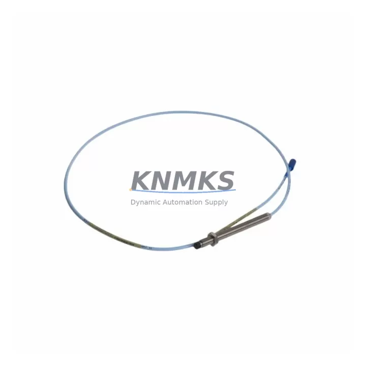
Overview
Bently Nevada 330103-00-19-10-01-00 Migration-Ready Proximity Transducer for Legacy Control Systems
The Bently Nevada 330103-00-19-10-01-00 is an eddy-current proximity transducer engineered for the 3300 XL Series monitoring platform, and it remains one of the most sought-after replacement components in legacy rotating machinery protection systems worldwide. As original equipment manufacturers phase out older vibration monitoring hardware, plant engineers and reliability teams increasingly rely on verified drop-in replacements like the 330103-00-19-10-01-00 to extend the operational life of existing control architectures without committing to a full system overhaul. Whether you are managing a turbine protection panel, a compressor train monitoring rack, or a critical pump monitoring loop, this transducer delivers the signal integrity and dimensional compatibility required for seamless field substitution.
Before initiating a replacement, engineers should confirm several key parameters. The 330103-00-19-10-01-00 operates on a standard -24 VDC bias voltage supply, and the receiving monitor card — typically a 3300/16 or 3300/20 series monitor — must be verified for input impedance compatibility. Terminal wiring follows the standard Bently Nevada coaxial cable convention: the center conductor carries the signal, the shield serves as the return path, and the outer jacket provides mechanical protection. When replacing a transducer in a live panel, it is critical to confirm that the existing extension cable — often a 330130 series armored extension cable — is undamaged and properly terminated at the junction box, as cable degradation is a common source of signal noise that can be misattributed to the transducer itself.
Backplane and rack interface compatibility is equally important. The 330103-00-19-10-01-00 mounts directly to the machinery casing using a standard 8mm threaded probe tip, and the gap voltage must be set within the linear range of -10 VDC to -18 VDC, with an optimal gap typically established at -12 VDC. During installation, a digital voltmeter should be used to verify gap voltage before the system is returned to service. If the existing monitor is a 3300/25 or 3300/46 series card, the channel configuration in the System 1 software or the local DIP switch settings must be reviewed to ensure the transducer sensitivity factor of 7.87 mV/µm (200 mV/mil) is correctly entered.
Migration Compatibility Table
| Parameter | 330103-00-19-10-01-00 | Notes / Retrofit Guidance |
|---|---|---|
| Probe Tip Thread | 8mm | Compatible with standard 3300 XL probe holders |
| Cable Length | 5m (integral) | Verify total system length with extension cable |
| Bias Voltage | -24 VDC | Confirm monitor card supply rail |
| Sensitivity | 7.87 mV/µm (200 mV/mil) | Must match monitor channel configuration |
| Linear Range | -10 to -18 VDC | Set gap at -12 VDC for optimal linearity |
| Monitor Compatibility | 3300/16, 3300/20, 3300/25, 3300/46 | Verify DIP switch or software sensitivity setting |
| Extension Cable | 330130 Series | Inspect for continuity and insulation integrity |
| Communication Protocol | Analog (4–20 mA / voltage output) | No protocol migration required for direct replacement |
| Installation Space | Standard probe holder clearance | Confirm radial clearance at machinery casing |
| Firmware Dependency | None (passive transducer) | Monitor firmware update may be required for new cards |
| Replacement Category | Direct drop-in for 330103 series | Cross-reference 330103-00-19-05-02-00 if cable length differs |
| Support terms | 12 Months | Covers manufacturing defects, signal output, and mechanical integrity |
Retrofit Planning for Existing Automation Systems
Successful integration of the 330103-00-19-10-01-00 into an existing monitoring architecture requires a structured approach to retrofit planning. In most legacy installations, the transducer is one component in a three-part measurement chain: the probe itself, the extension cable, and the Proximitor sensor (driver). The 3300 XL Proximitor — such as the 330180-91-00 or 330180-51-00 — conditions the raw eddy-current signal and outputs a calibrated voltage proportional to the gap distance. When replacing only the probe, the Proximitor must be retained and its output verified against the new transducer’s gap curve to confirm linearity across the full measurement range.
In control cabinet upgrades where the monitoring rack is being partially modernized, engineers often encounter mixed-generation hardware. A common scenario involves retaining the existing 3300/16 monitor cards while replacing worn transducers and extension cables. In these cases, the 330130-080-00-00 armored extension cable is the preferred interconnect, providing the correct characteristic impedance and mechanical protection for industrial environments. If the cabinet also houses a 3500 series rack — Bently Nevada’s next-generation platform — the 330103-00-19-10-01-00 can serve as a bridge component during phased migration, allowing the 3300 XL monitors to remain in service while 3500/42M or 3500/45 monitor cards are staged for installation in parallel slots.
For plants managing I/O expansion alongside transducer replacement, the signal outputs from the 330103-00-19-10-01-00 can be routed to a DCS or safety system via the monitor’s relay and analog output terminals. If the existing DCS interface relies on a 4–20 mA loop, the monitor card’s output scaling must be verified to match the engineering units configured in the DCS tag database. HMI screens displaying vibration trends should be reviewed to confirm that the tag names, engineering unit labels, and alarm setpoints remain consistent after the transducer swap. In Wonderware, FactoryTalk, or Ignition-based HMI environments, this typically involves a brief offline tag audit rather than a full screen rebuild.
Signal isolation is another consideration in older control cabinets where ground loops are common. Installing a signal isolator — such as a DIN-rail-mounted 4–20 mA isolator — between the monitor output and the DCS analog input card can eliminate noise introduced by ground potential differences between the machinery skid and the control room. This is particularly relevant in offshore or petrochemical environments where cable runs exceed 50 meters.
Downtime Control During System Migration
Minimizing unplanned downtime during a transducer replacement requires pre-staging all components before the maintenance window opens. For the 330103-00-19-10-01-00, this means having the replacement probe, the correct extension cable, a calibrated gap-setting tool, and a digital voltmeter on hand before the machinery is taken offline. The replacement procedure itself — disconnecting the old probe, threading in the new unit, setting the gap voltage, and verifying the Proximitor output — typically takes less than 30 minutes per measurement point when the work is pre-planned.
To protect existing program logic, the monitor’s relay outputs should be placed in bypass mode before the transducer is disconnected. This prevents nuisance trips from propagating to the safety system or DCS during the gap-setting procedure. In plants using a Bently Nevada System 1 condition monitoring platform, the channel can be placed in maintenance mode from the software interface, suppressing alarms without requiring changes to the underlying configuration. Once the new transducer is installed and the gap voltage is confirmed, the channel is returned to normal monitoring mode and the relay bypass is released.
For multi-point replacements — such as replacing all radial vibration transducers on a compressor train — a phased approach is recommended. Replacing one measurement plane at a time, verifying signal quality before proceeding to the next, reduces the risk of introducing multiple simultaneous faults. Each replaced transducer should be logged with its gap voltage reading, Proximitor output voltage, and the date of installation to support future maintenance records and support requests.
Pre-shipment testing is performed on every 330103-00-19-10-01-00 unit before dispatch. Each transducer is verified for correct sensitivity, linear range, and connector integrity. Units are shipped with a test report confirming compliance with Bently Nevada OEM specifications, supporting fast commissioning and reducing the risk of field failures during the critical post-installation period.
Retrofit Support FAQ
Q: Is the 330103-00-19-10-01-00 a direct replacement for other 330103 series variants?
A: Yes, the 330103-00-19-10-01-00 is dimensionally and electrically compatible with other 330103 series variants, including the 330103-00-19-05-02-00 and 330103-00-19-10-02-00, subject to cable length and connector type verification. Always confirm the total system cable length — probe plus extension — matches the Proximitor’s specified range.
Q: What commissioning steps are required after installation?
A: After threading the probe to the correct gap, connect the extension cable and Proximitor, then apply power and measure the DC gap voltage at the Proximitor output. Adjust the probe gap until the voltage reads within the linear range (-10 to -18 VDC), targeting -12 VDC. Verify the monitor card displays a valid vibration reading and that no fault or not-OK indicators are active before releasing the bypass.
Q: Can this transducer be used with a 3500 series monitor rack?
A: The 330103-00-19-10-01-00 is optimized for the 3300 XL platform. While the 3500 series uses the same eddy-current measurement principle, the 3500/42M and 3500/45 monitor cards are typically paired with 330500 or 330900 series transducers. Cross-platform use should be validated against the 3500 series transducer qualification matrix before field deployment.
Q: What does the support terms confirmed by quotation cover?
A: The support terms confirmed by quotation cover manufacturing defects, signal output accuracy within OEM specifications, and mechanical integrity of the probe body and connector. Units that fail within the confirmed support period are replaced or repaired at no charge. Support requests require the original test report and installation date documentation.
© 2026 KNMKS. All rights reserved.
Original Source: https://knmks.com
Contact: admin@knmks.com | +86 18359268345
Product Identification
- Brand / Ecosystem
-
Bently Nevada
Bently Nevada - Model / Series
-
330103-00-19-10-01-00
Bently Nevada 3300 XL / 3301 Series - Product Family
- Sensors
- Availability Status
- Available on request after model and quantity confirmation
- Inquiry Type
- B2B RFQ, replacement inquiry and project spare-part request
- Pre-Quote Check
- Exact SKU, brand, series, quantity, nameplate photos and destination country are checked before quotation
System Path
Where this product fits in the KNMKS automation structure.
Specification & Inquiry Focus
- Sensor range
- Photoelectric, proximity and process sensors
- Common needs
- Output type, distance and connector
- Project support
- Machine detection and replacement inquiry
Buyer Confirmation
Information KNMKS checks before replying.
- Exact model
- 330103-00-19-10-01-00
- Brand / ecosystem
- Bently Nevada
- Product family
- Sensors
- Application note
- Replacement, maintenance, project build or spare-part list
- Useful photos
- Nameplate, installed unit, cabinet layout or connector side
- Delivery details
- Quantity, destination country and target schedule
Document Support
Files and notes can be confirmed during quotation.
- Product photos or nameplate confirmation when available
- Packing and delivery notes before quotation confirmation
- Support scope and delivery terms confirmed per inquiry
- Export document coordination for qualified B2B requests
Inquiry Support
- NPN/PNP, analog and digital output checking
- Connector and cable compatibility review
- Fast inquiry support for maintenance teams
What to Send Us
- Brand and exact model number: Bently Nevada 330103-00-19-10-01-00
- Quantity and required delivery time
- Application, replacement requirement or nameplate photo
- Destination country and shipping preference
RFQ Preparation
This is a product inquiry page built for RFQ communication.
Fast Model Check
Send this model to KNMKS for confirmation.
Include quantity, destination country and photos if this is a maintenance replacement. The inquiry will be saved with a reference number after submission.
Brand & Compatibility Note
KNMKS displays automation product information for well-known industrial brand ecosystems and compatible replacement references. Brand names are used for product identification and compatibility reference only; final availability and commercial terms are confirmed per quotation.
 Manufacturing
 Machine Tools
 Packaging
 Energy & Power



 PLCs & Controllers
 HMI & Displays
 Servo Systems
 Variable Frequency Drives