
Overview
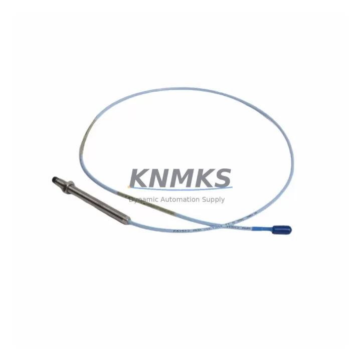
Bently Nevada 330103-00-18-50-02-CN Migration-Ready Proximity Transducer for Legacy Control Systems
The Bently Nevada 330103-00-18-50-02-CN is an 18mm proximity transducer engineered for the 3300 XL Series vibration monitoring platform. As legacy machinery protection systems age and OEM support windows close, plant engineers and reliability teams face mounting pressure to source verified drop-in replacements that preserve existing wiring infrastructure, signal conditioning chains, and monitoring logic without triggering full-system overhauls. The 330103-00-18-50-02-CN addresses this challenge directly: it is dimensionally and electrically compatible with the original Bently Nevada 3300 XL transducer specification, allowing retrofit teams to swap the sensor in the field while keeping the existing Proximitor® extension cable, junction box terminations, and monitor rack configuration intact.
Before committing to a replacement order, retrofit planners should verify several critical parameters. Power supply voltage to the transducer loop must fall within the –18 VDC to –24 VDC range that the 3300 XL Proximitor® driver module delivers. Terminal block wiring at the field junction box should be inspected for correct polarity and shield grounding continuity, particularly on installations where the original cable has been spliced or re-terminated over years of service. The gap voltage at the probe tip—typically set between –10.0 VDC and –10.4 VDC for a standard 50 mil (1.27 mm) air gap on steel targets—must be re-confirmed after installation using a calibrated DC voltmeter before the monitor is returned to service. If the existing Bently Nevada 3300 XL Proximitor® extension cable (such as the 330130 series) is being reused, inspect the cable jacket and connector pins for corrosion or mechanical damage that could introduce signal noise into the vibration channel.
Backplane and rack compatibility is equally important. The 330103-00-18-50-02-CN is designed to interface with the Bently Nevada 3300/16 or 3300/20 monitor modules housed in standard 19-inch rack enclosures. If the control cabinet is being upgraded from an older 7200 Series or 3500 Series rack to a 3300 XL architecture, the rack slot pitch, I/O terminal assignments, and channel address mapping must be re-validated in the System 1 configuration database before the new transducer is commissioned. Firmware version compatibility between the monitor module and the System 1 software revision should also be confirmed, as mismatched firmware can cause false alarm thresholds or incorrect full-scale output readings on the vibration display.
For plants migrating from discontinued Bently Nevada 7200 Series transducers to the 3300 XL platform, the 330103-00-18-50-02-CN serves as a validated migration path. The 7200 Series used a different sensitivity specification (200 mV/mil vs. the 3300 XL’s 100 mV/mil standard), so any existing alarm and danger setpoints in the monitor configuration must be recalculated and re-entered to reflect the new transducer’s output scale. HMI trend screens in the DCS or SCADA system that display shaft vibration in engineering units should be updated accordingly to prevent operators from misreading historical trend data against new baseline values.
Communication link integrity between the 3300 XL monitor rack and the plant DCS is another area requiring attention during migration. Many legacy installations use a Bently Nevada Data Manager or a Modbus RTU serial link to transmit vibration data to the control room. When replacing transducers as part of a broader rack upgrade, verify that the Modbus register map and baud rate settings in the 3300 XL monitor have not been altered, and confirm that the DCS driver is polling the correct register addresses for the updated channel assignments. In installations where a 3500 Series rack is being retained alongside the 3300 XL system, the two platforms may share a common TDXnet or Ethernet/IP network segment; ensure that IP address conflicts and network switch port configurations are resolved before live commissioning.
Installation space confirmation is a practical step that is often overlooked in retrofit planning. The 330103-00-18-50-02-CN has an 18mm probe body diameter and a standard armored cable exit. Verify that the existing probe holder or bracket in the bearing housing can accommodate the probe body without modification, and that the cable routing path to the junction box is free of sharp bends that could stress the coaxial cable. Where the original probe was installed with a custom-machined holder, the holder thread specification (typically M18×1.5 or 3/4-16 UNF) must match the replacement probe before installation proceeds.
Downtime during transducer replacement can be minimized by pre-staging the replacement unit with a verified gap voltage check on the bench using a Bently Nevada gap simulator or a precision resistor substitution box before the machine is taken offline. Having the replacement 330103-00-18-50-02-CN pre-gapped and documented reduces field adjustment time significantly. A pre-tested spare Bently Nevada 330130 extension cable and a set of terminal block ferrules should be staged alongside the transducer to avoid delays caused by damaged field hardware discovered only after the machine is shut down.
Migration Compatibility Table
| Parameter | 330103-00-18-50-02-CN | Legacy 7200 Series (Reference) | Notes |
|---|---|---|---|
| Probe Body Diameter | 18 mm | 8 mm / 11 mm / 25 mm (varies) | Verify probe holder thread before installation |
| Sensitivity | 100 mV/mil (3.937 V/mm) | 200 mV/mil (7.874 V/mm) | Recalculate alarm setpoints when migrating from 7200 Series |
| Supply Voltage | –18 VDC to –24 VDC | –18 VDC to –24 VDC | Compatible with existing 3300 XL Proximitor® driver |
| Linear Range | 50 mil (1.27 mm) nominal | Varies by model | Re-gap after installation; target –10.0 to –10.4 VDC |
| Cable Interface | 330130 Series extension cable | 7000 Series extension cable | Extension cable must be replaced when migrating from 7200 platform |
| Monitor Compatibility | 3300/16, 3300/20 monitor modules | 7200 Series monitors | Rack slot and terminal assignment must be re-validated |
| Communication Protocol | Modbus RTU / TDXnet / Ethernet/IP | Modbus RTU / proprietary serial | Confirm register map and baud rate after rack upgrade |
| Installation Space | Standard 18 mm armored probe | Varies | Confirm bearing housing bracket clearance |
| Firmware Compatibility | 3300 XL monitor firmware | 7200 Series firmware (not compatible) | Verify System 1 software revision before commissioning |
| Support terms | support terms confirmed by quotation — covers manufacturing defects and verified compatibility failures | ||
Retrofit Planning for Existing Automation Systems
A successful retrofit of the 330103-00-18-50-02-CN into an existing machinery protection system requires coordinated planning across several hardware layers. The transducer itself is only one element of the signal chain. The Bently Nevada 330130-080-00-00 extension cable connects the probe to the Proximitor® sensor, which conditions the raw eddy-current signal into a calibrated DC voltage output. If the existing extension cable has been in service for more than ten years or shows signs of jacket cracking or connector corrosion, it should be replaced concurrently with the transducer to avoid introducing a new failure point into a freshly commissioned channel.
The Proximitor® sensor itself—commonly the Bently Nevada 330180 or 330190 series—should be inspected for output drift. A Proximitor® that has aged out of its calibration window will produce incorrect gap voltage readings even with a new probe installed, leading to false vibration alarms or missed fault detection. Where the Proximitor® is mounted inside a field junction box exposed to high ambient temperatures or vibration, consider replacing it as a matched set with the 330103-00-18-50-02-CN to ensure the entire signal chain is operating within factory specification.
At the rack level, the 3300/16 or 3300/20 monitor module receives the conditioned signal and compares it against configured alarm and danger thresholds. During a transducer retrofit, the monitor’s channel configuration should be exported from System 1 before any hardware changes are made, preserving the existing setpoint database as a rollback reference. After the new transducer is installed and gapped, the channel should be verified in bypass mode before alarm outputs are re-enabled, preventing spurious trips to the emergency shutdown system during the commissioning window.
For plants that are simultaneously upgrading their control cabinet infrastructure, the retrofit may involve replacing an aging Bently Nevada 3500 Series rack with a 3300 XL rack. In this scenario, the I/O terminal block wiring from the field junction boxes must be re-terminated to match the 3300 XL rack’s connector pinout, and the System 1 configuration database must be rebuilt to reflect the new rack address and channel assignments. A Bently Nevada 1900/65 general-purpose equipment monitor or a 3500/42M proximitor monitor module may be used as an intermediate solution in mixed-platform installations where not all channels are being migrated simultaneously.
Signal isolation requirements should also be reviewed during retrofit planning. In installations where the vibration monitoring loop shares a common ground reference with a variable frequency drive (VFD) or other high-power switching equipment, a signal isolator may be required between the Proximitor® output and the monitor input to prevent common-mode noise from corrupting the vibration measurement. This is particularly relevant in retrofit projects where new VFD-driven pumps or compressors are being added to the same control cabinet that houses the 3300 XL rack.
Downtime Control During System Migration
Minimizing unplanned downtime during a transducer retrofit requires a structured pre-outage preparation process. Before the machine is taken offline, the replacement 330103-00-18-50-02-CN should be bench-tested using a gap simulator to confirm that the probe output voltage tracks linearly across the expected gap range. The probe serial number and calibration date should be recorded in the plant’s maintenance management system (CMMS) to establish a traceable service history for the new component.
During the outage window, the existing probe should be removed carefully to avoid damaging the probe holder threads in the bearing housing. If the holder shows signs of corrosion or thread damage, it should be re-tapped or replaced before the new probe is installed. The new 330103-00-18-50-02-CN should be installed to the manufacturer’s specified torque value and gapped to the target voltage using a calibrated DC voltmeter connected at the Proximitor® output terminals. Gap adjustment should be performed with the machine stationary and the shaft resting in its normal operating position.
Once the probe is gapped and the extension cable is connected, the monitor channel should be brought out of bypass mode one step at a time: first confirming the gap voltage is within the linear range, then verifying that the vibration reading is stable at a low noise floor with the machine still stationary, and finally confirming that the alarm and danger relay outputs respond correctly to a simulated over-range input before the machine is restarted. This staged commissioning approach protects the original program logic and alarm configuration from being inadvertently overwritten during the retrofit, and ensures that the control room operators see a clean, validated signal on their HMI vibration trend screens before the machine returns to service.
Post-commissioning, a 24-hour trend review in System 1 should be conducted to confirm that the new transducer is tracking shaft vibration consistently with the pre-outage baseline. Any deviation greater than 10% from the historical average at the same operating speed and load should be investigated before the machine is returned to full production load. Documenting the as-left gap voltage, vibration amplitude, and phase angle in the CMMS provides a validated baseline for future predictive maintenance comparisons.
Retrofit Support FAQ
Q: Is the 330103-00-18-50-02-CN a direct drop-in replacement for the original Bently Nevada 330103-00-18-50-02-CN?
A: Yes. The 330103-00-18-50-02-CN supplied by KNMKS is manufactured to the original Bently Nevada specification and is dimensionally and electrically compatible with the 3300 XL Proximitor® system. It uses the same 18mm probe body, the same 330130 series extension cable interface, and the same –18 VDC to –24 VDC supply voltage range as the original. No wiring modifications or monitor reconfiguration are required for a like-for-like replacement on an existing 3300 XL installation.
Q: What commissioning steps are required after installation?
A: After mechanical installation, the probe gap must be set to achieve a Proximitor® output voltage of –10.0 VDC to –10.4 VDC at the nominal 50 mil (1.27 mm) air gap. This is verified using a calibrated DC voltmeter at the Proximitor® output terminals. The monitor channel should then be brought out of bypass mode and the vibration reading confirmed stable before alarm outputs are re-enabled. A full channel functional test, including alarm and danger relay verification, is recommended before returning the machine to service.
Q: Does KNMKS provide pre-shipment testing, and what does the support terms confirmed by quotation cover?
A: Every 330103-00-18-50-02-CN unit shipped by KNMKS undergoes a pre-shipment functional test that verifies probe output linearity and gap voltage response across the full measurement range. The support terms confirmed by quotation cover manufacturing defects and verified compatibility failures under normal operating conditions. Support requests are supported by KNMKS’s technical team; contact admin@knmks.com with the unit serial number and a description of the observed fault.
Q: Can this transducer be used in a mixed-platform installation alongside a Bently Nevada 3500 Series rack?
A: The 330103-00-18-50-02-CN is designed for the 3300 XL platform and is not directly compatible with 3500 Series monitor modules, which use a different connector and channel configuration standard. In mixed-platform installations, the 3300 XL and 3500 Series racks operate as independent monitoring systems on separate channel assignments. If you are planning a phased migration from a 3500 Series rack to a 3300 XL architecture, KNMKS’s technical team can advise on sequencing the transducer replacements to minimize disruption to the overall machinery protection system.
© 2026 KNMKS. All rights reserved.
Original Source: https://knmks.com
Contact: admin@knmks.com | +86 18359268345
Product Identification
- Brand / Ecosystem
-
Bently Nevada
Bently Nevada - Model / Series
-
330103-00-18-50-02-CN
Bently Nevada 3300 XL / 3301 Series - Product Family
- Sensors
- Availability Status
- Available on request after model and quantity confirmation
- Inquiry Type
- B2B RFQ, replacement inquiry and project spare-part request
- Pre-Quote Check
- Exact SKU, brand, series, quantity, nameplate photos and destination country are checked before quotation
System Path
Where this product fits in the KNMKS automation structure.
Specification & Inquiry Focus
- Sensor range
- Photoelectric, proximity and process sensors
- Common needs
- Output type, distance and connector
- Project support
- Machine detection and replacement inquiry
Buyer Confirmation
Information KNMKS checks before replying.
- Exact model
- 330103-00-18-50-02-CN
- Brand / ecosystem
- Bently Nevada
- Product family
- Sensors
- Application note
- Replacement, maintenance, project build or spare-part list
- Useful photos
- Nameplate, installed unit, cabinet layout or connector side
- Delivery details
- Quantity, destination country and target schedule
Document Support
Files and notes can be confirmed during quotation.
- Product photos or nameplate confirmation when available
- Packing and delivery notes before quotation confirmation
- Support scope and delivery terms confirmed per inquiry
- Export document coordination for qualified B2B requests
Inquiry Support
- NPN/PNP, analog and digital output checking
- Connector and cable compatibility review
- Fast inquiry support for maintenance teams
What to Send Us
- Brand and exact model number: Bently Nevada 330103-00-18-50-02-CN
- Quantity and required delivery time
- Application, replacement requirement or nameplate photo
- Destination country and shipping preference
RFQ Preparation
This is a product inquiry page built for RFQ communication.
Fast Model Check
Send this model to KNMKS for confirmation.
Include quantity, destination country and photos if this is a maintenance replacement. The inquiry will be saved with a reference number after submission.
Brand & Compatibility Note
KNMKS displays automation product information for well-known industrial brand ecosystems and compatible replacement references. Brand names are used for product identification and compatibility reference only; final availability and commercial terms are confirmed per quotation.
 Manufacturing
 Machine Tools
 Packaging
 Energy & Power



 PLCs & Controllers
 HMI & Displays
 Servo Systems
 Variable Frequency Drives