
Overview
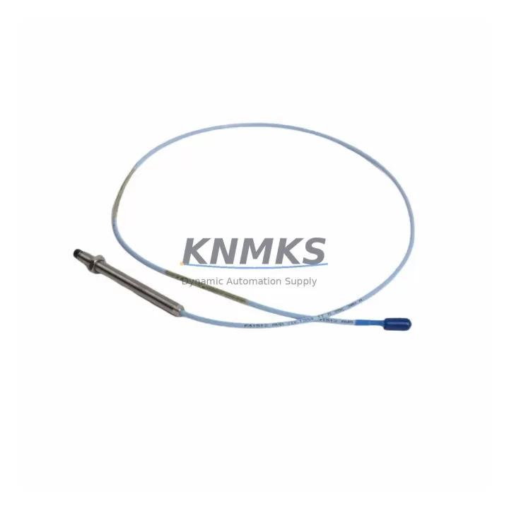
Bently Nevada 330103-00-18-15-02-00 Migration-Ready Proximity Transducer for Legacy Control Systems
The Bently Nevada 330103-00-18-15-02-00 is an 8mm eddy-current proximity transducer designed for the 3300 XL Series vibration monitoring platform. As original equipment reaches end-of-life and spare part availability tightens, this unit serves as a verified drop-in replacement for aging 3300 Series installations, enabling engineers to extend system service life without committing to a full platform migration. Whether you are restoring a tripped monitoring loop, replacing a mechanically damaged probe, or building a critical-spare inventory ahead of a planned shutdown, the 330103-00-18-15-02-00 delivers the dimensional accuracy, sensitivity, and cable length specification required to restore measurement integrity with minimal downtime.
The transducer operates within the standard Bently Nevada TK3 driver ecosystem. Before installation, engineers should confirm that the paired driver module — typically a 3300 XL 8mm Proximitor such as the 330180 series — is calibrated to the correct gap voltage range (nominally −10 VDC at 1.0 mm gap) and that the extension cable assembly matches the total system cable length for which the driver was originally calibrated. Mismatched cable lengths are a common source of scale-factor error during retrofit work and must be resolved before the loop is returned to service.
When integrating this transducer into an existing control cabinet, verify that the Proximitor power supply rail — typically −24 VDC — is within specification and that terminal block wiring follows the original three-wire topology: power, common, and signal output. If the cabinet also houses a 3500 Series rack, note that the 3500/42M proximity monitor accepts the same transducer family, allowing a phased migration path where the transducer hardware is standardized first while the monitor rack is upgraded in a subsequent outage window.
For installations where the original DCS or safety system reads the proximity signal through a 4–20 mA converter or a signal isolator, confirm that the isolator input impedance is compatible with the Proximitor output drive capability. Signal isolators from the same control platform family are preferred to avoid introducing ground loops that can corrupt vibration amplitude readings at low gap voltages.
Programming and HMI considerations are equally important. If the vibration monitoring data feeds into a DCS historian or a condition-monitoring software package, verify that the engineering-unit scaling — typically expressed in mils peak-to-peak or µm peak-to-peak — is preserved after the transducer swap. HMI faceplate alarm setpoints should be reviewed against the new transducer’s sensitivity specification to ensure that trip and alert thresholds remain valid. Where the original configuration file references a specific transducer serial number or calibration record, update the asset management database accordingly to maintain audit traceability.
Migration Compatibility Table
| Parameter | 330103-00-18-15-02-00 Specification | Retrofit / Migration Note |
|---|---|---|
| Probe Diameter | 8 mm | Direct fit for all 3300 XL 8mm probe mounts; confirm thread engagement depth |
| Cable Length (Probe) | 0.5 m (18 in) | Total system cable = probe + extension; must match driver calibration length |
| Extension Cable | 5.0 m (15 ft) — 330130-080-00-05 | Verify extension part number before ordering; length affects scale factor |
| Driver Compatibility | 3300 XL 8mm Proximitor (330180 series) | Also compatible with 3500/42M proximity monitor input channels |
| Output Signal | −10 VDC/mm (nominally) | Confirm DCS/safety system input range; isolator impedance check required |
| Power Supply | −24 VDC (from Proximitor) | Verify cabinet power rail capacity before adding replacement unit |
| Installation Space | Standard 8mm probe boss | Check radial clearance in bearing housing; confirm probe tip-to-shaft gap |
| Communication / Protocol | Analog voltage output | No firmware update required; protocol-agnostic analog signal |
| Replacement Relationship | Replaces legacy 330103 variants | Cross-reference original part number before procurement |
| Support terms | 12 Months | Covered from date of shipment; includes factory acceptance test record |
Retrofit Planning for Existing Automation Systems
A successful retrofit begins well before the maintenance window opens. Start by pulling the original loop drawing to identify every component in the signal chain: the 330103-00-18-15-02-00 probe, the extension cable assembly, the 330180-series Proximitor, the terminal block assignments in the junction box, and the monitor card slot address within the 3300 XL rack. If the rack also carries a 3300 XL 16-channel I/O expander or a dedicated keyphasor module, document their slot positions so that the replacement probe can be assigned to the correct channel without disturbing adjacent measurement loops.
Power budget verification is a step that is frequently skipped and frequently regretted. The −24 VDC supply feeding the Proximitor must have sufficient headroom to support the replacement unit under worst-case load. If the cabinet power supply is already near capacity — particularly in older installations where additional I/O modules or communication gateways have been added over the years — a load calculation should be performed before the outage begins. Adding a 24 VDC DIN-rail power supply module as a dedicated feed for the new transducer loop is a low-cost insurance measure that eliminates supply-rail interaction as a diagnostic variable during commissioning.
Wiring adaptation is straightforward for like-for-like replacements, but engineers should inspect the existing terminal block for corrosion, loose ferrules, and insulation degradation before reusing it. In cabinets where the original wiring used unshielded twisted pair, consider upgrading to shielded cable during the retrofit to reduce susceptibility to variable-frequency drive interference — a common noise source in modernized production lines where legacy monitoring hardware coexists with newer drive technology.
If the plant is executing a broader migration from the 3300 platform toward the 3500 Series rack architecture, the 330103-00-18-15-02-00 transducer remains fully compatible with the 3500/42M proximity monitor, providing a natural bridge that allows the probe and cabling infrastructure to be retained while the monitor rack is upgraded. This phased approach reduces the scope of any single outage and allows the instrumentation team to validate each segment of the signal chain independently before the system is returned to continuous operation.
Downtime Control During System Migration
Minimizing unplanned downtime during a proximity transducer replacement requires a structured pre-outage checklist and a clearly defined rollback procedure. Before the maintenance window begins, the replacement 330103-00-18-15-02-00 unit should be bench-tested against a calibrated gap simulator to confirm output voltage linearity across the full measurement range. This factory acceptance test record should accompany the unit to site and be filed in the asset management system alongside the original calibration certificate.
During the outage, the original program logic in the DCS or safety PLC should not be modified unless a firmware incompatibility is identified. The transducer swap is a hardware-layer change; the control logic, alarm setpoints, and historian tag assignments should remain frozen until the new transducer has been confirmed in service. This discipline protects the original program logic and ensures that any anomaly observed during commissioning can be attributed unambiguously to the hardware change rather than a concurrent software modification.
Gap setting is the most time-sensitive step in the commissioning sequence. With the machine at rest, adjust the probe gap to achieve the target DC output voltage — typically −10 VDC at 1.0 mm gap for standard 8mm transducers — and lock the probe in position before the machine is brought back online. Confirm that the Proximitor OK output is asserted and that the monitor channel is not in a latched-trip state before releasing the equipment to operations. A brief coast-down vibration check, if operationally feasible, provides additional confidence that the replacement transducer is tracking shaft motion correctly before the unit is returned to full-load operation.
Maintaining field control continuity throughout the process requires clear communication between the instrumentation team, the control room operator, and the operations supervisor. A defined hold point — where the operator confirms that the DCS display is showing a valid, in-range signal before the maintenance team withdraws — reduces the risk of a nuisance trip caused by an unseated connector or an incorrectly set gap voltage being interpreted as a genuine machine fault.
Retrofit Support FAQ
Q: Is the 330103-00-18-15-02-00 a direct replacement for other 330103 suffix variants?
A: The 330103 series uses a structured part-number convention where each suffix segment encodes probe diameter, cable length, connector type, and temperature rating. The -00-18-15-02-00 suffix specifies an 8mm probe with a 0.5 m probe cable, 5.0 m extension, standard connector, and standard temperature range. Variants with different cable lengths or temperature ratings are not interchangeable without recalibrating the paired Proximitor driver. Always cross-reference the full part number before procurement.
Q: What commissioning steps are required after installation?
A: After mechanical installation, set the probe gap to achieve the target DC bias voltage using a calibrated digital voltmeter at the Proximitor output terminals. Verify the OK relay output is asserted, confirm the monitor channel is not in a bypassed or latched state, and check that the DCS historian is receiving a valid engineering-unit value. Document the as-found and as-left gap voltage in the maintenance record.
Q: How is the replacement unit tested before shipment?
A: Each 330103-00-18-15-02-00 unit is tested for output voltage linearity, insulation resistance, and connector integrity prior to shipment. A factory acceptance test record is included with the unit. Stock is maintained to support same-week dispatch for urgent replacement requirements.
Q: What support terms coverage applies to this replacement unit?
A: A support terms confirmed by quotation is provided from the date of shipment, covering manufacturing defects and performance deviations from the published specification. Support requests should be submitted with the original shipment documentation and a description of the observed fault condition.
© 2026 KNMKS. All rights reserved.
Original Source: https://knmks.com
Contact: admin@knmks.com | +86 18359268345
Product Identification
- Brand / Ecosystem
-
Bently Nevada
Bently Nevada - Model / Series
-
330103-00-18-15-02-00
Bently Nevada 3300 XL / 3301 Series - Product Family
- Sensors
- Availability Status
- Available on request after model and quantity confirmation
- Inquiry Type
- B2B RFQ, replacement inquiry and project spare-part request
- Pre-Quote Check
- Exact SKU, brand, series, quantity, nameplate photos and destination country are checked before quotation
System Path
Where this product fits in the KNMKS automation structure.
Specification & Inquiry Focus
- Sensor range
- Photoelectric, proximity and process sensors
- Common needs
- Output type, distance and connector
- Project support
- Machine detection and replacement inquiry
Buyer Confirmation
Information KNMKS checks before replying.
- Exact model
- 330103-00-18-15-02-00
- Brand / ecosystem
- Bently Nevada
- Product family
- Sensors
- Application note
- Replacement, maintenance, project build or spare-part list
- Useful photos
- Nameplate, installed unit, cabinet layout or connector side
- Delivery details
- Quantity, destination country and target schedule
Document Support
Files and notes can be confirmed during quotation.
- Product photos or nameplate confirmation when available
- Packing and delivery notes before quotation confirmation
- Support scope and delivery terms confirmed per inquiry
- Export document coordination for qualified B2B requests
Inquiry Support
- NPN/PNP, analog and digital output checking
- Connector and cable compatibility review
- Fast inquiry support for maintenance teams
What to Send Us
- Brand and exact model number: Bently Nevada 330103-00-18-15-02-00
- Quantity and required delivery time
- Application, replacement requirement or nameplate photo
- Destination country and shipping preference
RFQ Preparation
This is a product inquiry page built for RFQ communication.
Fast Model Check
Send this model to KNMKS for confirmation.
Include quantity, destination country and photos if this is a maintenance replacement. The inquiry will be saved with a reference number after submission.
Brand & Compatibility Note
KNMKS displays automation product information for well-known industrial brand ecosystems and compatible replacement references. Brand names are used for product identification and compatibility reference only; final availability and commercial terms are confirmed per quotation.
 Manufacturing
 Machine Tools
 Packaging
 Energy & Power



 PLCs & Controllers
 HMI & Displays
 Servo Systems
 Variable Frequency Drives