
Overview
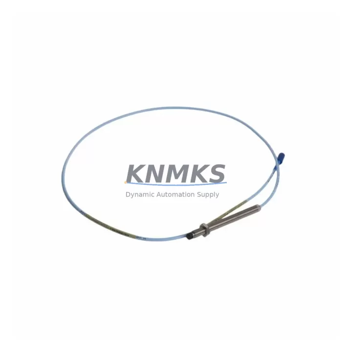
Bently Nevada 330103-00-16-20-02-00 3300 XL Migration-Ready Proximity Transducer: Legacy System Retrofit & Compatibility Upgrade
The Bently Nevada 330103-00-16-20-02-00 is an 8mm proximity transducer engineered for the 3300 XL series continuous machinery monitoring platform. As industrial facilities worldwide accelerate the retirement of aging vibration monitoring infrastructure, this transducer has become a critical component in legacy system migration projects — serving as a verified drop-in replacement for discontinued 3300 series transducers and enabling seamless integration into both existing and upgraded monitoring architectures.
Whether your facility is executing a full control system overhaul or performing targeted spare-part replacement to extend the operational life of an existing 3300 XL rack, the 330103-00-16-20-02-00 delivers the electrical and mechanical compatibility required to minimize engineering risk and reduce unplanned downtime. Its standardized 5-meter integral cable, -18.5 VDC nominal supply voltage, and 200 mV/mil (7.87 V/mm) sensitivity make it directly interchangeable with earlier 330103 series variants across a wide range of rotating machinery applications including compressors, turbines, pumps, and gearboxes.
Migration Compatibility Table
| Parameter | Specification / Retrofit Note |
|---|---|
| SKU / Part Number | 330103-00-16-20-02-00 |
| Series | Bently Nevada 3300 XL |
| Probe Diameter | 8mm |
| Cable Length | 5m (16 ft) integral armored cable |
| Sensitivity | 200 mV/mil (7.87 V/mm) |
| Supply Voltage | -18.5 VDC nominal (compatible with 3300 XL driver/monitor) |
| Output Range | -1 VDC to -17 VDC linear |
| Connector Interface | Standard 3300 XL driver input — no adapter required |
| Mounting Thread | M10 x 1 — verify existing bracket thread before installation |
| Legacy Replacement For | 330103-00-16-10-02-00, 330103-00-16-05-02-00, earlier 3300 series 8mm probes |
| Communication Compatibility | Analog 4–20 mA / voltage output; compatible with 3300 XL monitor cards and DCS analog input modules |
| Installation Space | Confirm probe tip clearance gap (typically 1.0–2.0 mm) and bracket reach before replacement |
| Firmware / Configuration | No firmware required; monitor card scale factor must match 200 mV/mil sensitivity setting |
| Commissioning Check | Verify gap voltage at static shaft, confirm OK/NOT OK relay thresholds in monitor card |
| Support terms | 12 months from date of shipment — covers manufacturing defects and electrical performance |
Retrofit Planning for Existing Automation Systems
Successful integration of the 330103-00-16-20-02-00 into a legacy or modernized monitoring system requires careful pre-installation planning across several engineering disciplines. The transducer operates as part of a three-component measurement chain: the probe itself, a compatible extension cable (such as the Bently Nevada 330130-080-00-00 or equivalent 3300 XL series extension cable), and a driver/oscillator module (typically the Bently Nevada 330180-X1-05 proximitor sensor). All three components must be matched in series length and sensitivity to maintain system calibration. If the existing extension cable is being reused from a prior installation, verify that its total series resistance and capacitance remain within the driver’s specified input range.
At the monitor card level, the 3300 XL rack accepts the transducer signal through dedicated channel input terminals on monitor modules such as the 3300/16 or 3300/20 series cards. Before hot-swapping a failed transducer, confirm that the monitor card channel is placed in bypass mode to prevent spurious trip signals from propagating to the DCS or safety instrumented system. If the facility’s control architecture routes vibration data through a Modbus RTU or PROFIBUS DP gateway module installed in the 3300 XL rack, verify that the channel address mapping in the gateway configuration file corresponds to the physical slot position of the replacement transducer — particularly if the rack layout has been modified since the original commissioning.
For facilities migrating from an older 3300 series rack to a 3300 XL platform, the physical rack and backplane dimensions differ. The 3300 XL rack accepts standard 19-inch panel mounting and uses a dedicated backplane bus for power distribution and inter-module communication. Confirm available rack slot count and power supply headroom before adding new monitor cards. The Bently Nevada 3300/05 power supply module or its replacement equivalent must be sized to support the total current draw of all installed monitor and I/O modules. In high-channel-count installations, a secondary power supply module may be required to maintain redundancy.
Where the legacy system included a Keyphasor module (such as the 3300/25 or 3300/55 series) for phase reference and speed measurement, confirm that the Keyphasor signal routing is preserved during the transducer replacement. Loss of Keyphasor reference will disable vector-based vibration analysis and may trigger nuisance alarms in the DCS historian. If the HMI display screens have been configured with channel-specific alarm setpoints and trend displays, coordinate with the control room operator to verify that the new transducer’s gap voltage and sensitivity match the values embedded in the HMI configuration — particularly in systems where the HMI communicates directly with the 3300 XL rack via an OPC DA or OPC UA server.
Downtime Control During System Migration
Minimizing production interruption during a proximity transducer replacement requires a structured pre-outage preparation protocol. Before the maintenance window opens, the replacement 330103-00-16-20-02-00 should be bench-tested using a portable proximitor power supply and a calibrated target disk to verify gap voltage linearity and output signal integrity. This pre-shipment functional test — which is performed on every unit prior to dispatch — confirms that the transducer meets Bently Nevada’s original performance specification and eliminates the risk of installing a defective component during a time-critical outage.
During the outage, the recommended sequence is: (1) place the affected monitor card channel in bypass, (2) de-energize the proximitor driver, (3) disconnect the extension cable at the driver input, (4) remove the failed probe from the machinery bracket, (5) install the replacement 330103-00-16-20-02-00 and torque the mounting nut to specification, (6) reconnect the extension cable, (7) re-energize the driver and verify gap voltage at the monitor card terminal, and (8) remove bypass and confirm OK status. This sequence preserves the original program logic in the monitor card and DCS without requiring any configuration changes, provided the replacement transducer’s sensitivity and cable length match the original system design.
For facilities operating under a safety instrumented system that receives a hardwired trip signal from the 3300 XL monitor, coordinate with the SIS engineer to place the relevant SIS input in maintenance override before beginning the replacement. Restore the SIS input only after the new transducer has been verified in service and the monitor card has confirmed a valid, in-range gap voltage. This approach eliminates the risk of a spurious machine trip during the replacement procedure and protects both the equipment and the production schedule.
All units are shipped with full traceability documentation and are available from in-stock inventory, supporting same-day or next-day dispatch for urgent maintenance requirements. The support terms confirmed by quotation cover all manufacturing defects and electrical performance deviations from the published specification.
Retrofit Support FAQ
Q: Is the 330103-00-16-20-02-00 a direct replacement for earlier 330103 series part numbers with different cable length suffixes?
A: The 330103 series uses a standardized suffix structure where the cable length is encoded in the part number. The -16- segment in 330103-00-16-20-02-00 denotes a 5-meter (16-foot) cable. If your existing installation uses a different cable length variant (e.g., -10- for 3 meters or -05- for 1.5 meters), the replacement must match the original cable length to maintain the calibrated series resistance of the measurement chain. Substituting a different cable length without recalibrating the driver will introduce a gap voltage offset error.
Q: What commissioning steps are required after installing the replacement transducer?
A: After physical installation, measure the static gap voltage at the monitor card input terminal with the shaft at rest. The gap voltage should fall within the linear range specified for the 3300 XL monitor card (typically -10 VDC ± 2 VDC at the nominal 1.0–2.0 mm air gap). Adjust the probe position in the bracket to achieve the target gap voltage, then lock the mounting nut. Confirm that the monitor card displays an OK status and that the vibration channel reads near-zero at rest. Record the as-left gap voltage in the maintenance management system for future reference.
Q: Has this unit been tested before shipment, and what does the support terms confirmed by quotation cover?
A: Yes. Every 330103-00-16-20-02-00 unit undergoes a functional output test prior to dispatch, verifying gap voltage linearity, sensitivity, and cable continuity. The support terms confirmed by quotation cover manufacturing defects, electrical performance deviations from specification, and cable integrity. It does not cover damage resulting from incorrect installation, mechanical impact, or operation outside the specified supply voltage range. Support requests are supported by our technical team at admin@knmks.com.
Q: Is inventory available for immediate shipment, and can you supply multiple units for a fleet replacement project?
A: In-stock inventory is maintained to support both single-unit emergency replacements and multi-unit fleet projects. Lead times for standard quantities are typically 1–3 business days. For large-quantity orders or scheduled maintenance programs requiring guaranteed availability over an extended period, contact our sales team to discuss a blanket order arrangement with reserved stock allocation.
© 2026 KNMKS. All rights reserved.
Original Source: https://knmks.com
Contact: admin@knmks.com | +86 18359268345
Product Identification
- Brand / Ecosystem
-
Bently Nevada
Bently Nevada - Model / Series
-
330103-00-16-20-02-00
Bently Nevada 3300 XL / 3301 Series - Product Family
- Sensors
- Availability Status
- Available on request after model and quantity confirmation
- Inquiry Type
- B2B RFQ, replacement inquiry and project spare-part request
- Pre-Quote Check
- Exact SKU, brand, series, quantity, nameplate photos and destination country are checked before quotation
System Path
Where this product fits in the KNMKS automation structure.
Specification & Inquiry Focus
- Sensor range
- Photoelectric, proximity and process sensors
- Common needs
- Output type, distance and connector
- Project support
- Machine detection and replacement inquiry
Buyer Confirmation
Information KNMKS checks before replying.
- Exact model
- 330103-00-16-20-02-00
- Brand / ecosystem
- Bently Nevada
- Product family
- Sensors
- Application note
- Replacement, maintenance, project build or spare-part list
- Useful photos
- Nameplate, installed unit, cabinet layout or connector side
- Delivery details
- Quantity, destination country and target schedule
Document Support
Files and notes can be confirmed during quotation.
- Product photos or nameplate confirmation when available
- Packing and delivery notes before quotation confirmation
- Support scope and delivery terms confirmed per inquiry
- Export document coordination for qualified B2B requests
Inquiry Support
- NPN/PNP, analog and digital output checking
- Connector and cable compatibility review
- Fast inquiry support for maintenance teams
What to Send Us
- Brand and exact model number: Bently Nevada 330103-00-16-20-02-00
- Quantity and required delivery time
- Application, replacement requirement or nameplate photo
- Destination country and shipping preference
RFQ Preparation
This is a product inquiry page built for RFQ communication.
Fast Model Check
Send this model to KNMKS for confirmation.
Include quantity, destination country and photos if this is a maintenance replacement. The inquiry will be saved with a reference number after submission.
Brand & Compatibility Note
KNMKS displays automation product information for well-known industrial brand ecosystems and compatible replacement references. Brand names are used for product identification and compatibility reference only; final availability and commercial terms are confirmed per quotation.
 Manufacturing
 Machine Tools
 Packaging
 Energy & Power



 PLCs & Controllers
 HMI & Displays
 Servo Systems
 Variable Frequency Drives