
Overview
Bently Nevada 330103-00-15-50-02-CN Migration-Ready Proximity Transducer: Legacy System Migration and Compatible Upgrade
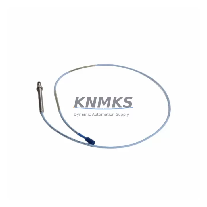
The Bently Nevada 330103-00-15-50-02-CN is a 3300 XL Series eddy current proximity transducer engineered for continuous shaft vibration and position monitoring in rotating machinery. As legacy Bently Nevada 3300 Series systems approach end-of-life or face discontinued spare parts availability, this migration-ready replacement module provides a direct, validated upgrade path for facilities operating turbines, compressors, pumps, and gearboxes under continuous monitoring requirements.
When planning a retrofit from an aging 3300 Series installation, engineers must verify several critical parameters before committing to a replacement. Power supply compatibility is the first checkpoint: the 330103-00-15-50-02-CN operates on a standard –24 VDC bias supply delivered through the Bently Nevada 3300 XL proximitor/seismic monitor, and the existing field wiring must be confirmed to carry the correct voltage without excessive line drop. Terminal block wiring at the junction box should be inspected for correct polarity, shield grounding, and cable continuity before the new transducer is installed.
The transducer’s 5-metre extension cable and 2-metre armored probe cable assembly must be routed to match the original cable path. Any deviation in total system cable length will shift the calibrated gap voltage and require recalibration of the proximitor output. When replacing a unit in a running plant, it is strongly recommended to document the original gap voltage reading—typically between –10 VDC and –18 VDC depending on shaft material—before removal, so the replacement can be set to the same operating point during commissioning.
Backplane and rack interface compatibility is another key consideration. The 330103-00-15-50-02-CN connects to the Bently Nevada 3300 XL monitor rack via the standard BNC or integral connector interface. If the existing rack is a first-generation 3300 Series rather than the 3300 XL platform, a rack adapter or monitor module upgrade—such as migrating to the 3300/16 or 3300/20 monitor cards—may be required to maintain signal chain integrity. In some installations, the Bently Nevada 3500 Series rack system is the target migration platform, and in those cases the 330103-00-15-50-02-CN can serve as an interim transducer while the monitor cards are upgraded in a phased approach.
Program and HMI compatibility must also be addressed. DCS or PLC systems receiving the 4–20 mA or voltage output from the Bently Nevada monitor will need their scaling parameters verified. If the plant historian or vibration analysis software—such as System 1—is configured with alarm setpoints tied to the original transducer’s sensitivity factor (typically 7.87 mV/µm or 200 mV/mil), those values must be confirmed unchanged after replacement. HMI faceplate displays showing gap, direct, and 1X/2X vibration vectors should be validated against the new transducer output before returning the machine to service.
Communication link integrity between the Bently Nevada rack and the plant DCS should be verified after installation. Whether the system uses a Modbus RTU serial link, a 4–20 mA hardwired connection, or a Bently Nevada Data Manager interface, the signal path must be loop-checked end-to-end. In facilities where the 3300 XL rack communicates with a Rockwell Automation ControlLogix or Allen-Bradley PLC via a serial gateway, the gateway configuration should be reviewed to confirm that the channel address mapping for the replaced transducer channel remains correct.
Installation space confirmation is straightforward for this transducer: the probe tip diameter and thread specification (M10 × 1 standard) match the original mounting boss in most OEM machinery designs. However, if the bearing housing has been modified or the probe holder has been replaced with a non-standard fitting, a physical measurement of the available probe travel range should be taken to ensure the 2-metre probe cable can reach the junction box without excessive bending radius.
Firmware version compatibility is not a concern at the transducer level, as the 330103-00-15-50-02-CN is a passive eddy current device with no embedded firmware. However, the proximitor monitor module firmware version should be confirmed to support the transducer’s target material calibration curve if the shaft material differs from the standard AISI 4140 steel reference.
Downtime during replacement can be minimized by pre-staging the new transducer assembly, pre-setting the gap to the documented operating voltage using a calibration fixture, and preparing all terminal connections in advance. A typical hot-swap replacement on a machine that can be briefly unloaded takes 30–45 minutes per transducer channel, including gap setting and loop verification.
All units are supplied with a support terms confirmed by quotation covering manufacturing defects and are subject to pre-shipment functional testing including gap voltage verification, insulation resistance check, and cable continuity confirmation. Inventory is maintained for fast dispatch to support unplanned outage recovery scenarios.
Migration Compatibility Table
| Parameter | 330103-00-15-50-02-CN (This Unit) | Legacy 3300 Series Reference | Notes |
|---|---|---|---|
| Probe Thread | M10 × 1 | M10 × 1 | Direct fit to standard OEM mounting boss |
| Extension Cable Length | 5 m | 5 m | Total system length must match calibration |
| Probe Cable Length | 2 m | 2 m | Verify routing clearance |
| Bias Supply | –24 VDC | –24 VDC | Confirm line voltage at junction box |
| Sensitivity | 7.87 mV/µm (200 mV/mil) | 7.87 mV/µm (200 mV/mil) | Verify DCS/historian scaling unchanged |
| Target Material | AISI 4140 Steel (standard) | AISI 4140 Steel | Recalibrate if shaft material differs |
| Connector Interface | BNC / Integral | BNC / Integral | Confirm rack connector type before ordering |
| Monitor Rack Compatibility | 3300 XL Series | 3300 / 3300 XL | Adapter may be needed for first-gen 3300 rack |
| Communication Output | Via monitor module (4–20 mA / Modbus) | Via monitor module | Loop-check after replacement |
| Installation Space | Standard probe holder | Standard probe holder | Measure travel range if holder modified |
| Firmware | N/A (passive device) | N/A | Confirm monitor module firmware if needed |
| Support terms | 12 Months | — | Covers manufacturing defects; pre-ship tested |
Retrofit Planning for Existing Automation Systems
A successful retrofit of the 330103-00-15-50-02-CN into an existing automation system requires coordinated planning across multiple hardware layers. The transducer itself interfaces with the Bently Nevada 3300 XL proximitor monitor, which in turn feeds vibration data to the plant control system. In a typical turbine control cabinet, the monitor rack may sit alongside a Bently Nevada 3500/22M transient data interface module, a 3500/42M proximitor monitor, or a 3500/45 position monitor—all of which share the same backplane power bus and must remain operational during a single-channel transducer swap.
The field junction box connecting the transducer to the monitor rack typically uses a Bently Nevada 330130 or 330180 series junction box with labeled terminal strips for the probe, extension cable, and shield drain. Verifying terminal torque and shield continuity at this junction point is a mandatory step before energizing the replacement transducer. In older installations, the junction box terminals may show oxidation or loose connections that contribute to signal noise—these should be cleaned and re-torqued as part of the retrofit.
Where the plant is migrating from a 3300 Series rack to a 3500 Series rack as part of a broader control system upgrade, the 330103-00-15-50-02-CN transducer remains compatible with the 3500 platform when paired with the appropriate 3500/42M or 3500/44M monitor module. This phased approach—replacing transducers first, then upgrading monitor cards—allows the plant to spread capital expenditure across multiple maintenance windows while maintaining continuous vibration protection.
In facilities where a Rockwell Automation ControlLogix PLC or a Siemens S7-300 series controller receives vibration data via a serial gateway or analog input card, the I/O channel configuration must be reviewed after any transducer replacement. The analog input scaling in the PLC program should reflect the transducer’s 200 mV/mil sensitivity, and any alarm deadband or filter time constant settings should be re-validated against the new transducer’s noise floor. A Bently Nevada 3300 XL system communicating over Modbus RTU to a gateway device will require a register map verification to confirm that the replaced channel’s data address is correctly mapped in the SCADA or DCS historian.
For plants using a Bently Nevada System 1 condition monitoring platform, the transducer replacement event should be logged in the System 1 database with the new serial number and calibration data. The System 1 configuration for the affected measurement point should be reviewed to confirm that the transducer type, sensitivity, and gap range are correctly defined, as these parameters drive the automated alarm and alert logic that protects the machine.
Downtime Control During System Migration
Minimizing unplanned downtime during a transducer replacement requires a structured pre-outage preparation process. Before the machine is taken offline, the maintenance team should document the current gap voltage, direct vibration amplitude, and 1X vector for the affected channel. This baseline data serves as the acceptance criterion for the replacement transducer: after installation and gap setting, the new transducer should reproduce the same gap voltage within ±0.5 VDC and the same vibration amplitude within ±10% under identical operating conditions.
The replacement transducer assembly should be pre-staged with the probe gap pre-set using a calibration block or a digital gap meter referenced to the target shaft material. This eliminates the need for iterative gap adjustment in the field and reduces the time the machine must remain offline. All terminal connections at the junction box should be pre-labeled and the replacement cable routed to the junction box before the machine is shut down, so that the actual transducer swap is limited to disconnecting the old probe and connecting the new one.
Original program logic in the PLC or DCS should not be modified during a transducer replacement unless a known incompatibility is identified. The goal is to restore the original control behavior with the new hardware, not to introduce new logic changes that could mask or create faults. If the replacement transducer requires a sensitivity recalibration due to a different shaft material, that change should be made in the monitor module configuration—not in the PLC program—to preserve the integrity of the original control logic.
After the replacement transducer is installed and the machine is returned to service, a 24-hour monitoring period is recommended during which the vibration data from the replaced channel is compared against the historical baseline and against adjacent channels on the same machine. Any deviation from the expected trend should be investigated before the machine is returned to full load. This monitoring period also provides an opportunity to verify that the communication link between the Bently Nevada rack and the plant DCS is transmitting the correct data for the replaced channel.
By following this structured approach, most transducer replacements can be completed within a single 4–8 hour maintenance window, including pre-staging, installation, gap setting, loop verification, and post-installation monitoring setup. For critical machines where any unplanned trip carries significant production cost, a hot spare transducer assembly—pre-gapped and pre-tested—should be maintained in the plant spare parts inventory to enable same-shift replacement in the event of a transducer failure.
Retrofit Support FAQ
Q: Is the 330103-00-15-50-02-CN a direct replacement for the original Bently Nevada 330103-00-15-50-02-CN?
A: Yes. This unit is a direct form, fit, and function replacement for the original Bently Nevada 330103-00-15-50-02-CN proximity transducer. It uses the same M10 × 1 probe thread, 5-metre extension cable, 2-metre probe cable, and –24 VDC bias supply, and is compatible with the Bently Nevada 3300 XL monitor rack without modification.
Q: What pre-shipment testing is performed on each unit?
A: Each unit undergoes gap voltage verification, insulation resistance testing between the probe body and cable shield, and cable continuity confirmation before shipment. A test report is available upon request. All units are covered by a support terms confirmed by quotation against manufacturing defects.
Q: How do I verify wiring compatibility before installation?
A: Confirm that the existing junction box terminal strip is wired for the standard Bently Nevada three-wire configuration (probe, extension cable center conductor, and shield drain). Measure the bias supply voltage at the junction box terminals with the monitor energized—it should read between –18 VDC and –26 VDC. If the voltage is outside this range, the monitor module power supply should be inspected before installing the replacement transducer.
Q: What is the lead time and inventory availability?
A: Units are maintained availability confirmed by RFQ for immediate dispatch. Standard orders ship within 1–3 business days. For urgent outage recovery requirements, expedited shipping is available. Contact our sales team to confirm current inventory levels and delivery options for your location.
© 2026 KNMKS. All rights reserved.
Original Source: https://knmks.com
Contact: admin@knmks.com | +86 18359268345
Product Identification
- Brand / Ecosystem
-
Bently Nevada
Bently Nevada - Model / Series
-
330103-00-15-50-02-CN
Bently Nevada 3300 XL / 3301 Series - Product Family
- Sensors
- Availability Status
- Available on request after model and quantity confirmation
- Inquiry Type
- B2B RFQ, replacement inquiry and project spare-part request
- Pre-Quote Check
- Exact SKU, brand, series, quantity, nameplate photos and destination country are checked before quotation
System Path
Where this product fits in the KNMKS automation structure.
Specification & Inquiry Focus
- Sensor range
- Photoelectric, proximity and process sensors
- Common needs
- Output type, distance and connector
- Project support
- Machine detection and replacement inquiry
Buyer Confirmation
Information KNMKS checks before replying.
- Exact model
- 330103-00-15-50-02-CN
- Brand / ecosystem
- Bently Nevada
- Product family
- Sensors
- Application note
- Replacement, maintenance, project build or spare-part list
- Useful photos
- Nameplate, installed unit, cabinet layout or connector side
- Delivery details
- Quantity, destination country and target schedule
Document Support
Files and notes can be confirmed during quotation.
- Product photos or nameplate confirmation when available
- Packing and delivery notes before quotation confirmation
- Support scope and delivery terms confirmed per inquiry
- Export document coordination for qualified B2B requests
Inquiry Support
- NPN/PNP, analog and digital output checking
- Connector and cable compatibility review
- Fast inquiry support for maintenance teams
What to Send Us
- Brand and exact model number: Bently Nevada 330103-00-15-50-02-CN
- Quantity and required delivery time
- Application, replacement requirement or nameplate photo
- Destination country and shipping preference
RFQ Preparation
This is a product inquiry page built for RFQ communication.
Fast Model Check
Send this model to KNMKS for confirmation.
Include quantity, destination country and photos if this is a maintenance replacement. The inquiry will be saved with a reference number after submission.
Brand & Compatibility Note
KNMKS displays automation product information for well-known industrial brand ecosystems and compatible replacement references. Brand names are used for product identification and compatibility reference only; final availability and commercial terms are confirmed per quotation.
 Manufacturing
 Machine Tools
 Packaging
 Energy & Power



 PLCs & Controllers
 HMI & Displays
 Servo Systems
 Variable Frequency Drives