
Overview
Bently Nevada 330103-00-09-10-02-CN Migration-Ready Proximity Transducer for Legacy Control Systems
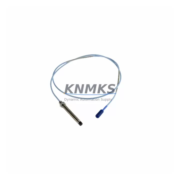
The Bently Nevada 330103-00-09-10-02-CN is a 9-meter extension cable proximity transducer from the 3300 XL Series, engineered for eddy-current-based shaft vibration and position monitoring in rotating machinery. As legacy Bently Nevada 3300 Series installations approach end-of-support cycles, this unit serves as a direct migration-ready replacement, maintaining full signal compatibility with existing 3300 XL proximitor/driver assemblies, DCS input cards, and vibration monitoring panels without requiring rewiring or reconfiguration of the host system.
For plants operating aging turbine protection systems, compressor trains, or pump monitoring racks, the 330103-00-09-10-02-CN provides a validated drop-in path that preserves the original 4–20 mA or voltage output signal chain. Engineers planning a retrofit must confirm the proximitor driver model — typically the 3300 XL 8mm Proximitor Sensor (330180 series) — remains installed and operational, as the transducer and driver form a calibrated pair. Substituting only the transducer without verifying driver compatibility is a common source of calibration drift during migration.
Migration Compatibility Table
| Parameter | 330103-00-09-10-02-CN | Legacy 3300 Series Reference |
|---|---|---|
| Series | 3300 XL | 3300 / 3300 XL |
| Cable Length | 9 m (extension) | 5 m / 9 m options |
| Probe Tip Diameter | 8 mm | 8 mm |
| Transduction Method | Eddy Current | Eddy Current |
| Output Signal | –24 VDC bias / 200 mV/mil | –24 VDC bias / 200 mV/mil |
| Compatible Proximitor | 330180 / 330181 series | 330180 / 330181 series |
| Connector Type | MIL-C-5015 (CN suffix) | MIL-C-5015 |
| Installation Clearance | Standard bearing housing mount | Standard bearing housing mount |
| Communication / Protocol | Analog (passive sensor) | Analog (passive sensor) |
| Replacement Recommendation | Direct drop-in for 330103 variants | Verify driver pairing before swap |
| Commissioning Focus | Gap voltage, scale factor, OK relay | Gap voltage, scale factor, OK relay |
| Support terms | support terms confirmed by quotation — All units ship tested | |
Retrofit Planning for Existing Automation Systems
A successful retrofit of the 330103-00-09-10-02-CN into an existing vibration monitoring architecture requires a structured pre-installation review. Begin by auditing the current rack configuration: most 3300 XL installations use a 3500 Series Machinery Protection System rack or a standalone 3300 rack, and the transducer signal is routed through a dedicated proximitor driver module before reaching the monitor card. Confirm that the 330180-series proximitor driver is within its calibration interval and that the interconnect cable routing from the bearing housing to the junction box does not exceed the total system cable length specification.
Terminal wiring for the CN connector variant follows the standard Bently Nevada color-coded scheme: verify shield grounding at one end only to prevent ground loops, which are a frequent source of noise in retrofitted panels. If the existing conduit run uses armored cable, inspect for insulation degradation before reusing it with the new transducer. For installations where the original cable tray is shared with power conductors, signal isolation may be required — a DIN-rail-mounted signal isolator or barrier module is recommended to maintain measurement integrity.
Plants migrating from older 3300 non-XL transducers to the 3300 XL platform should also review the monitor card firmware version. The 3500/40M and 3500/42M monitor cards require firmware that supports the XL scale factor; older firmware revisions may misinterpret the output and trigger false OK relay trips. Coordinate with the control room team to schedule a brief offline window for firmware verification before the transducer swap. During this window, the 3500 rack’s I/O module assignments and channel configuration should be exported and saved as a backup — this protects the existing alarm setpoints, danger limits, and Keyphasor channel assignments.
For plants also upgrading their HMI displays, note that vibration trend screens referencing the old transducer tag name will need to be updated in the SCADA or DCS historian. If the site uses a System 1 Evolution software platform for condition monitoring, the device configuration file for the replaced transducer should be updated to reflect the new serial number and calibration data. This ensures that historical trend data remains traceable and that alarm correlation functions correctly after the swap.
Where the retrofit scope extends beyond a single transducer — for example, replacing all proximity probes on a compressor train — consider sequencing the work by bearing location to maintain partial machine monitoring during the campaign. A 3500 rack with redundant power supply modules (such as the 3500/15 Power Supply) allows one channel group to remain active while adjacent channels are being serviced, significantly reducing the risk window for unmonitored operation.
Downtime Control During System Migration
Minimizing downtime during a proximity transducer replacement requires preparation that begins well before the maintenance window opens. The 330103-00-09-10-02-CN should be bench-tested prior to installation: connect it to a known-good 330180 proximitor driver, apply the nominal –24 VDC supply, and verify the output gap voltage falls within the linear range (typically –10 to –18 VDC for an 8 mm probe at the recommended gap). This pre-installation verification eliminates the most common cause of extended commissioning time — discovering a wiring or compatibility issue only after the machine is taken offline.
During the swap, preserve the original program logic in the 3500 monitor by placing the affected channel in bypass mode rather than removing the configuration. Bypass mode maintains the rack’s communication link to the DCS or safety system, preventing spurious trips or loss-of-signal alarms from propagating to the control room while the transducer is disconnected. Once the new 330103-00-09-10-02-CN is installed and the gap voltage is confirmed, remove the bypass and perform a live signal check against the machine’s known vibration baseline before returning the channel to normal monitoring.
For sites where the 3500 rack communicates via Modbus RTU or OPC-DA to a distributed control system, confirm that the communication link remains active throughout the swap. A brief interruption in the Modbus poll cycle can cause the DCS to log a communication fault, which may require a manual acknowledgment before the historian resumes data collection. Coordinating with the DCS operator in advance to suppress this alarm class during the maintenance window prevents unnecessary alarm floods and keeps the control room log clean.
All units supplied are pre-tested and shipped with a support terms confirmed by quotation. In-stock inventory is available for immediate dispatch, supporting urgent replacement scenarios where machine availability is critical. Lead time for standard orders is typically 1–3 business days from confirmation.
Retrofit Support FAQ
Q: Is the 330103-00-09-10-02-CN a direct replacement for other 330103 suffix variants?
A: The 330103 series uses a structured part number where the suffix defines cable length, connector type, and temperature rating. The -00-09-10-02-CN variant specifies a 9-meter extension cable with a MIL-C-5015 CN-style connector. It is directly interchangeable with other -CN suffix variants of the same cable length. Variants with different cable lengths (e.g., 5 m) or connector styles require verification before substitution. Contact our technical team with your existing part number for a confirmed cross-reference.
Q: What commissioning checks are required after installation?
A: After physical installation, set the probe gap to the manufacturer-specified distance (typically 1.0–1.5 mm for an 8 mm probe) and measure the output voltage at the proximitor driver terminals. The gap voltage should fall within the linear range specified on the calibration certificate. Verify the OK relay status on the 3500 monitor card, confirm the vibration reading is within the machine’s normal baseline, and check that the DCS historian is receiving updated values before closing the maintenance work order.
Q: Can this transducer be used with non-Bently Nevada monitor cards?
A: The 330103-00-09-10-02-CN outputs a standard eddy-current signal compatible with any monitor card designed for the Bently Nevada 3300 XL signal standard (–24 VDC excitation, 200 mV/mil scale factor). Third-party vibration monitors that accept this signal standard — including certain Emerson and Metrix monitor cards — may be compatible, but full system validation is the responsibility of the site engineer. We recommend bench-testing the complete signal chain before committing to a non-OEM monitor pairing.
Q: What does the support terms confirmed by quotation cover, and what is your stock availability?
A: The support terms confirmed by quotation cover manufacturing defects and verified performance failures under normal operating conditions. Each unit is functionally tested before shipment. We maintain in-stock inventory for immediate dispatch; orders confirmed before the daily cut-off are typically shipped the same business day. For large-quantity requirements or long-term supply agreements, contact our sales team to discuss stocking arrangements and lead-time commitments.
© 2026 KNMKS. All rights reserved.
Original Source: https://knmks.com
Contact: admin@knmks.com | +86 18359268345
Product Identification
- Brand / Ecosystem
-
Bently Nevada
Bently Nevada - Model / Series
-
330103-00-09-10-02-CN
Bently Nevada 3300 XL / 3301 Series - Product Family
- Sensors
- Availability Status
- Available on request after model and quantity confirmation
- Inquiry Type
- B2B RFQ, replacement inquiry and project spare-part request
- Pre-Quote Check
- Exact SKU, brand, series, quantity, nameplate photos and destination country are checked before quotation
System Path
Where this product fits in the KNMKS automation structure.
Specification & Inquiry Focus
- Sensor range
- Photoelectric, proximity and process sensors
- Common needs
- Output type, distance and connector
- Project support
- Machine detection and replacement inquiry
Buyer Confirmation
Information KNMKS checks before replying.
- Exact model
- 330103-00-09-10-02-CN
- Brand / ecosystem
- Bently Nevada
- Product family
- Sensors
- Application note
- Replacement, maintenance, project build or spare-part list
- Useful photos
- Nameplate, installed unit, cabinet layout or connector side
- Delivery details
- Quantity, destination country and target schedule
Document Support
Files and notes can be confirmed during quotation.
- Product photos or nameplate confirmation when available
- Packing and delivery notes before quotation confirmation
- Support scope and delivery terms confirmed per inquiry
- Export document coordination for qualified B2B requests
Inquiry Support
- NPN/PNP, analog and digital output checking
- Connector and cable compatibility review
- Fast inquiry support for maintenance teams
What to Send Us
- Brand and exact model number: Bently Nevada 330103-00-09-10-02-CN
- Quantity and required delivery time
- Application, replacement requirement or nameplate photo
- Destination country and shipping preference
RFQ Preparation
This is a product inquiry page built for RFQ communication.
Fast Model Check
Send this model to KNMKS for confirmation.
Include quantity, destination country and photos if this is a maintenance replacement. The inquiry will be saved with a reference number after submission.
Brand & Compatibility Note
KNMKS displays automation product information for well-known industrial brand ecosystems and compatible replacement references. Brand names are used for product identification and compatibility reference only; final availability and commercial terms are confirmed per quotation.
 Manufacturing
 Machine Tools
 Packaging
 Energy & Power



 PLCs & Controllers
 HMI & Displays
 Servo Systems
 Variable Frequency Drives