
Overview
Bently Nevada 330103-00-03-10-01-05 Migration-Ready Proximity Probe for Legacy Control Systems
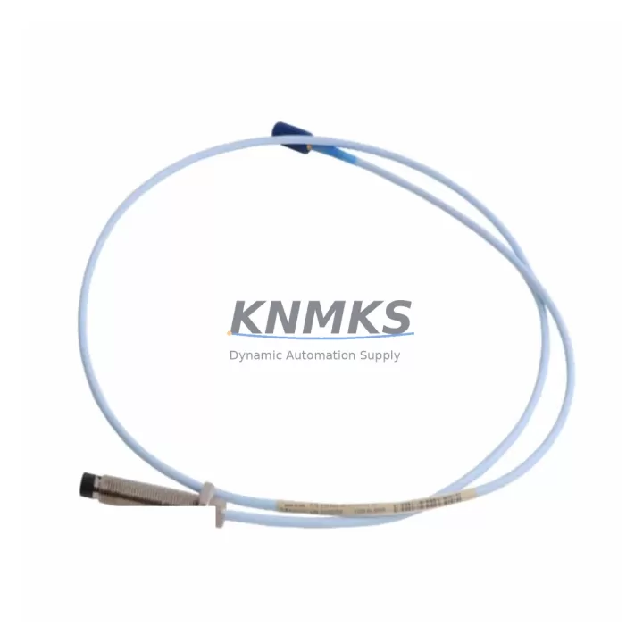
The Bently Nevada 330103-00-03-10-01-05 is a 3300 XL Series eddy-current proximity probe engineered for direct drop-in replacement in legacy vibration monitoring and machinery protection systems. With a 5-metre (16.4 ft) integral cable, 8 mm probe tip diameter, and standard -18 VDC driver supply compatibility, this unit is fully interchangeable with original 3300 XL field installations without requiring re-cabling, re-ranging, or driver reconfiguration. For plant engineers managing aging turbomachinery protection panels, this probe eliminates the most common retrofit risk: signal chain recalibration after a component swap.
Industrial facilities operating GE, Siemens, or legacy Bently Nevada 3300 Series racks frequently encounter discontinued probe assemblies during scheduled overhauls or unplanned failures. The 330103-00-03-10-01-05 is stocked as a verified migration-ready spare, tested against OEM output sensitivity specifications (7.87 V/mm ± 0.1 V/mm) and gap voltage linearity curves before shipment. Each unit ships with a factory test report and is covered by a support terms confirmed by quotation from the date of delivery.
Migration Compatibility Table
| Parameter | 330103-00-03-10-01-05 Specification | Retrofit / Migration Note |
|---|---|---|
| Probe Series | Bently Nevada 3300 XL | Direct replacement for 3300 XL field probes; no rack modification required |
| Tip Diameter | 8 mm | Confirm existing probe boss thread: 3/8-24 UNF; no re-boring required |
| Cable Length | 5 m (16.4 ft) integral | Verify extension cable (330130 Series) length matches original installation |
| Driver Compatibility | 3300 XL 8 mm Driver (330180 Series) | Confirm driver firmware version supports 8 mm probe; update if below Rev. D |
| Output Sensitivity | 7.87 V/mm ± 0.1 V/mm | Re-verify gap voltage at installation: target -10.0 VDC ± 0.5 VDC at nominal gap |
| Supply Voltage | -18 VDC (from driver) | Confirm power supply module (e.g., 3500/15 Power Supply) output is within spec |
| Installation Thread | 3/8-24 UNF | Use OEM probe guard and lock nut; torque to 1.7 N·m (15 in-lb) |
| Communication / Protocol | Analogue (4–20 mA / voltage output via driver) | No protocol migration required; signal feeds directly into 3500 rack I/O modules |
| Rack / Backplane Interface | 3500 Series Rack (3500/42M, 3500/45, 3500/46M) | Confirm channel assignment and OK/Not-OK relay wiring in rack configuration |
| Support terms | 12 Months from delivery | Includes factory test report; support terms void if probe tip is mechanically damaged |
Retrofit Planning for Existing Automation Systems
A successful 330103-00-03-10-01-05 retrofit begins well before the probe reaches the machine. Plant engineers should first audit the complete signal chain: the probe itself, the 330130-080-00-00 extension cable connecting it to the driver, and the 330180-X1-05 driver module seated in the 3500 rack. If the existing extension cable shows insulation degradation or connector corrosion, replacing it simultaneously with the probe eliminates a second unplanned outage. The 3500/42M Proximitor I/O Module channel configuration should be exported from System 1 or the 3500 Rack Configuration Software before any hardware swap — this preserves alarm setpoints, OK limits, and Keyphasor assignments that would otherwise require manual re-entry.
For installations where the 3300 XL rack is being retired in favour of a 3500 Series rack migration, the 330103-00-03-10-01-05 probe is fully compatible with the new rack’s input requirements, making it a bridge component that supports a phased migration strategy. During the transition period, the probe can continue feeding the legacy 3300 rack while the 3500 rack is commissioned in parallel, provided the driver supply voltage is independently sourced. The 3500/15 Power Supply Module should be verified for adequate current headroom when adding channels during phased expansion.
Where HMI screens in the control room display vibration trend data sourced from the 3300 rack, the migration plan must include a screen update cycle. Operators relying on Bently Nevada System 1 or third-party SCADA displays (such as those integrated via Modbus RTU through a 3500/92 Communication Gateway Module) should validate that tag names and engineering unit scaling remain consistent after the probe swap. A mismatch in sensitivity scaling between the old and new probe — even within the ±0.1 V/mm tolerance band — can shift displayed vibration amplitude by several microns, which may trigger nuisance alarms during the first post-installation run.
Signal isolation is another consideration in older control cabinets where ground loops are common. If the existing installation uses a signal isolator between the driver output and the DCS analogue input card, verify that the isolator’s input impedance is compatible with the driver’s output impedance. Replacing the probe without addressing a pre-existing ground loop will not resolve intermittent noise on the vibration channel. In such cases, a DIN-rail mounted signal conditioner rated for -18 VDC proximity probe signals should be added to the retrofit BOM.
Downtime Control During System Migration
Minimising machine downtime during a proximity probe replacement requires a structured pre-outage preparation protocol. Before the maintenance window opens, the replacement 330103-00-03-10-01-05 unit should be bench-tested using a calibration target and a reference driver to confirm output sensitivity and OK voltage are within specification. This pre-verification step eliminates the risk of installing a unit that fails its first power-on check at the machine, which would extend the outage by the time required to source and re-test a second probe.
During the outage, the original probe’s gap voltage reading should be recorded before disconnection — this serves as the baseline for re-gapping the new probe. The replacement probe should be installed, gapped to the same nominal air gap (typically 1.0–1.5 mm for 8 mm probes on steel targets), and the gap voltage re-measured at the driver terminal before the rack is returned to service. If the 3500 rack is configured for automatic OK/Not-OK latching, the channel should be manually reset after the probe is confirmed in-gap to prevent a spurious trip during the first machine start.
For facilities with redundant measurement channels (X-Y probe pairs), the second channel remains active during single-probe replacement, maintaining continuous vibration monitoring throughout the maintenance window. This redundancy is a key advantage of the 3500 Series rack architecture and should be documented in the site’s maintenance procedure to ensure operators do not unnecessarily trip the machine during a single-channel probe swap. After the replacement is complete, a short coast-down or bump test is recommended to verify that the new probe’s output tracks correctly against the redundant channel before the machine is returned to full load.
Retrofit Support FAQ
Q1: Is the 330103-00-03-10-01-05 a direct replacement for the older 330103-00-03-10-00-05?
A: Yes. The suffix change from -00-05 to -01-05 reflects a cable jacket material update (from standard PVC to oil-resistant PVC) introduced in a later production revision. Electrical performance, sensitivity, thread specification, and driver compatibility are identical. No driver reconfiguration or gap re-ranging is required when substituting the -01-05 for the -00-05 in an existing installation.
Q2: What commissioning checks are required after installation?
A: After mechanical installation and gapping, verify: (1) OK voltage at the driver terminal is within the specified window (typically -10.0 VDC ± 0.5 VDC); (2) the 3500 rack channel shows an OK status with no latched alarms; (3) vibration amplitude displayed in System 1 or the SCADA is consistent with the pre-outage baseline at the same machine speed. If the amplitude reading differs by more than 5% from the pre-outage value at the same operating condition, re-check the air gap and extension cable continuity before returning the machine to service.
Q3: Do you supply the matching 330130 extension cable and 330180 driver as a kit?
A: Yes. The 330103-00-03-10-01-05 can be supplied as a standalone probe or as part of a complete 3300 XL signal chain kit including the 330130-080-00-00 extension cable and the 330180-X1-05 driver module. Kitting eliminates the risk of component mismatch and simplifies incoming inspection. Contact our sales team for kit pricing and lead time.
Q4: What is the support terms coverage and what does the shipment include?
A: Every 330103-00-03-10-01-05 unit is covered by a support terms confirmed by quotation from the date of delivery. Each shipment includes the probe assembly, a factory test report confirming output sensitivity and OK voltage measurements, and a calibration data sheet. Units are shipped in anti-static packaging with foam protection to prevent tip damage in transit. Support requests are processed within 5 business days of receipt of the returned unit.
© 2026 KNMKS. All rights reserved.
Original Source: https://knmks.com
Contact: admin@knmks.com | +86 18359268345
Product Identification
- Brand / Ecosystem
-
Bently Nevada
Bently Nevada - Model / Series
-
330103-00-03-10-01-05
Bently Nevada 3300 XL / 3301 Series - Product Family
- Sensors
- Availability Status
- Available on request after model and quantity confirmation
- Inquiry Type
- B2B RFQ, replacement inquiry and project spare-part request
- Pre-Quote Check
- Exact SKU, brand, series, quantity, nameplate photos and destination country are checked before quotation
System Path
Where this product fits in the KNMKS automation structure.
Specification & Inquiry Focus
- Sensor range
- Photoelectric, proximity and process sensors
- Common needs
- Output type, distance and connector
- Project support
- Machine detection and replacement inquiry
Buyer Confirmation
Information KNMKS checks before replying.
- Exact model
- 330103-00-03-10-01-05
- Brand / ecosystem
- Bently Nevada
- Product family
- Sensors
- Application note
- Replacement, maintenance, project build or spare-part list
- Useful photos
- Nameplate, installed unit, cabinet layout or connector side
- Delivery details
- Quantity, destination country and target schedule
Document Support
Files and notes can be confirmed during quotation.
- Product photos or nameplate confirmation when available
- Packing and delivery notes before quotation confirmation
- Support scope and delivery terms confirmed per inquiry
- Export document coordination for qualified B2B requests
Inquiry Support
- NPN/PNP, analog and digital output checking
- Connector and cable compatibility review
- Fast inquiry support for maintenance teams
What to Send Us
- Brand and exact model number: Bently Nevada 330103-00-03-10-01-05
- Quantity and required delivery time
- Application, replacement requirement or nameplate photo
- Destination country and shipping preference
RFQ Preparation
This is a product inquiry page built for RFQ communication.
Fast Model Check
Send this model to KNMKS for confirmation.
Include quantity, destination country and photos if this is a maintenance replacement. The inquiry will be saved with a reference number after submission.
Brand & Compatibility Note
KNMKS displays automation product information for well-known industrial brand ecosystems and compatible replacement references. Brand names are used for product identification and compatibility reference only; final availability and commercial terms are confirmed per quotation.
 Manufacturing
 Machine Tools
 Packaging
 Energy & Power



 PLCs & Controllers
 HMI & Displays
 Servo Systems
 Variable Frequency Drives