
Overview
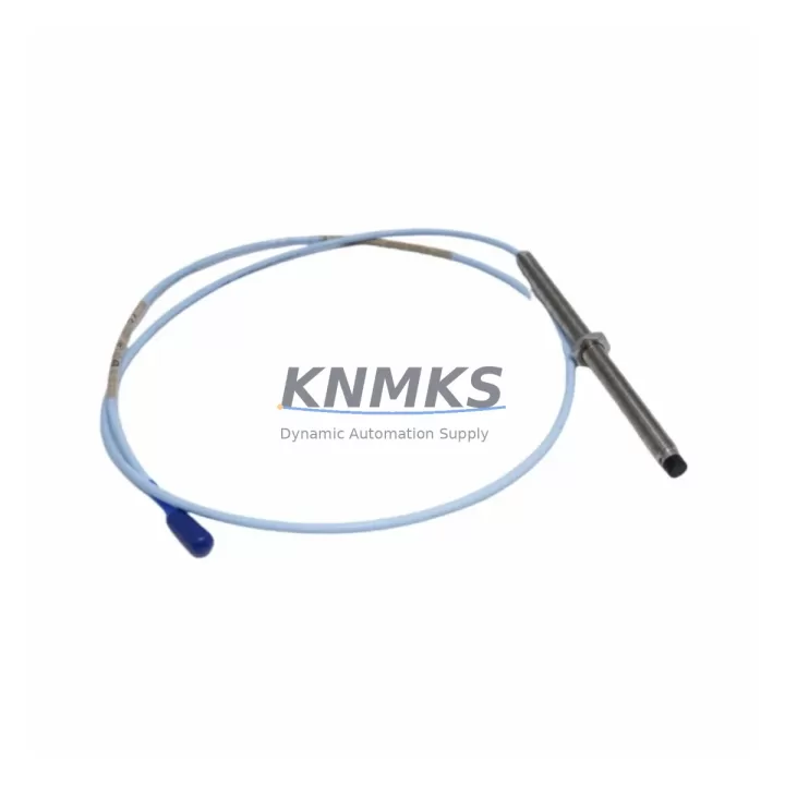
Bently Nevada 330103-00-02-05-02-05 3300 XL Proximity Transducer: Migration-Ready Replacement for Legacy Vibration Monitoring Systems
The Bently Nevada 330103-00-02-05-02-05 is an 8mm proximity transducer designed for the 3300 XL series vibration monitoring platform. As industrial facilities continue to phase out aging condition monitoring infrastructure, this unit serves as a direct, migration-ready replacement for obsolete or end-of-life proximity transducers in rotating machinery protection systems. Whether you are restoring a turbine protection loop, upgrading a compressor monitoring rack, or replacing a failed sensor in a critical asset protection chain, the 330103-00-02-05-02-05 delivers verified compatibility with existing 3300 XL monitor cards, extension cables, and driver electronics without requiring reprogramming of the host system.
When planning a retrofit around this transducer, engineers must confirm several key parameters before installation. Power supply requirements for the 3300 XL driver typically call for a regulated -24 VDC supply; verify that the existing power module in the monitoring rack — such as a 3300/20 power supply unit — can sustain the additional load if multiple transducers are being replaced simultaneously. Terminal wiring at the junction box must match the original color-coded scheme: confirm shield grounding practice, especially in high-EMI environments near variable frequency drives or large motor starters. The extension cable — commonly a 330130-series armored cable — must be length-matched to maintain the correct gap voltage range at the driver output. Substituting a non-matched cable length will shift the linear operating range and introduce measurement error that may not be immediately apparent during commissioning.
Backplane interface and slot addressing within the 3300 XL rack should be documented before removal of the old transducer system. The monitor card address, channel assignment, and full-scale range setting stored in the 3300/16 or 3300/46 monitor must be recorded and verified against the replacement transducer’s sensitivity specification (nominally 7.87 V/mm or 200 mV/mil). If the facility uses a System 1 condition monitoring software platform for trend data and alarm management, confirm that the channel tag, engineering unit scaling, and alarm setpoints are preserved in the database before the physical swap. Failure to do so can result in nuisance trips or, more critically, undetected alarm suppression after the retrofit.
HMI screen updates are often overlooked during transducer replacements. If the control room display or DCS faceplate references the old transducer tag or serial number for maintenance tracking, update the graphic element and associated historian tag to reflect the new unit. Communication links between the 3300 XL rack and the plant DCS — whether via 4–20 mA analog output, Modbus RTU, or a dedicated System 1 OPC server — should be verified for signal continuity after the replacement is complete. A loop check using a calibrated milliamp source at the monitor output terminals will confirm that the analog signal chain is intact before returning the machine to service.
Installation space within the monitoring cabinet should be confirmed prior to ordering. The 330103-00-02-05-02-05 uses a standard M8 threaded body with a 5mm sensing range and requires a clear radial path to the shaft target surface. If the existing probe holder or armored conduit fitting is corroded or mechanically damaged, plan to replace the 330180-series probe holder assembly at the same time to avoid a second outage. Firmware version compatibility is not a concern for this passive transducer, but the associated 3300/16 monitor card firmware should be at a revision level that supports the transducer’s sensitivity coefficient — consult the monitor card revision history if the rack has not been updated in several years.
For facilities managing a broader vibration monitoring modernization program, the 330103-00-02-05-02-05 is frequently deployed alongside the 330130-080-00-00 extension cable, the 330180-X1-05 proximity probe holder, and the 3300/16 dual-channel monitor card. In multi-shaft train applications, the 3300/46 position monitor is often installed in the same rack to handle axial position measurement, sharing the same -24 VDC power bus. Where the legacy system includes a 3300/55 keyphasor module for phase reference, verify that the keyphasor gap voltage is within specification after any rack disturbance, as mechanical vibration during transducer replacement can shift the probe gap on adjacent channels.
Migration Compatibility Table
| Parameter | Detail |
|---|---|
| SKU / Part Number | 330103-00-02-05-02-05 |
| Series | Bently Nevada 3300 XL |
| Probe Diameter | 8mm |
| Sensing Range | 5mm (linear range) |
| Sensitivity | 7.87 V/mm (200 mV/mil) |
| Supply Voltage | -24 VDC (from 3300 XL driver / power module) |
| Compatible Monitor Cards | 3300/16, 3300/46, 3300/55 (same rack) |
| Compatible Extension Cable | 330130-series (length-matched required) |
| Compatible Probe Holder | 330180-series |
| Installation Thread | M8 threaded body |
| Communication Interface | 4–20 mA analog output; Modbus RTU; System 1 OPC |
| Replacement Recommendation | Direct drop-in for 330103-series 8mm probes in 3300 XL racks |
| Commissioning Check Points | Gap voltage, sensitivity calibration, loop check, HMI tag update |
| Support terms | support terms confirmed by quotation |
Retrofit Planning for Existing Automation Systems
A successful retrofit begins with a complete bill-of-materials audit of the existing monitoring rack. In a typical 3300 XL installation, the rack may contain a mix of the 3300/16 dual-channel vibration monitor, the 3300/46 position monitor, and the 3300/55 keyphasor module, all powered by a 3300/20 power supply. When replacing the 330103-00-02-05-02-05 transducer, the field engineer should document the current gap voltage reading at the driver output — typically between -10 VDC and -18 VDC for a properly gapped 8mm probe — before disconnecting the old unit. This baseline reading serves as the acceptance criterion for the replacement probe after installation.
The 330130-series extension cable is a critical component in the signal chain. Unlike standard instrument cable, the extension cable is electrically matched to the transducer and driver as a system; substituting a cable of a different length or from a different manufacturer will alter the system sensitivity and may cause the monitor card to report a fault condition. If the existing cable is damaged or of unknown provenance, replace it with a new 330130-080-00-00 or length-appropriate variant at the same time as the transducer. The 330180-series probe holder should also be inspected for thread damage, corrosion, or mechanical deformation; a damaged holder can prevent accurate gap setting and introduce vibration-induced measurement noise.
For facilities that have already migrated their condition monitoring data to a System 1 Evolution platform, the channel configuration for the replacement transducer can be imported from a saved rack configuration file, significantly reducing commissioning time. If the plant is still running an older System 1 version, a manual channel re-entry may be required, and the historian archive should be backed up before any configuration changes are made to preserve long-term trend data.
Downtime Control During System Migration
Minimizing unplanned downtime during a proximity transducer replacement requires a structured pre-outage preparation process. Before the maintenance window opens, the replacement 330103-00-02-05-02-05 should be bench-tested using a driver/monitor test kit to verify that the probe output voltage falls within the specified linear range at a known gap distance. This pre-shipment functional test, which is performed on every unit we supply, eliminates the risk of installing a defective component and discovering the fault only after the machine is back online.
During the outage, the original program logic in the associated safety or control system should not be modified. The 3300 XL monitor card stores its configuration in non-volatile memory; however, if the monitor card itself is being replaced as part of a broader upgrade, the configuration should be exported and saved before the card is removed. Alarm bypass procedures should be coordinated with the control room to prevent spurious trips during the gap-setting procedure, which requires the probe to be moved through its linear range while the machine is stationary.
After installation, a structured loop check sequence — gap voltage verification, sensitivity confirmation, and a simulated vibration input using a calibrated shaker or signal injector — should be completed before the bypass is lifted. If the machine protection system is connected to an emergency shutdown system, the ESD logic should remain in bypass until the loop check is signed off by the responsible engineer. Documenting the as-found and as-left gap voltage readings in the maintenance management system creates a traceable record that supports future reliability analysis and spare parts planning.
Retrofit Support FAQ
Q: Is the 330103-00-02-05-02-05 a direct replacement for other 330103-series probes?
A: Yes. The 330103-00-02-05-02-05 is dimensionally and electrically compatible with other 330103-series 8mm proximity probes used in 3300 XL systems, provided the extension cable length and driver type are matched. Always verify the gap voltage specification against the monitor card’s acceptance range before returning the machine to service.
Q: What commissioning steps are required after installation?
A: After mechanical installation, set the probe gap to achieve an output voltage within the monitor card’s specified linear range (typically -10 VDC to -18 VDC). Perform a loop check to verify the 4–20 mA or digital output signal at the DCS or System 1 interface. Update the HMI tag and historian configuration if required, and lift the alarm bypass only after the loop check is complete and documented.
Q: Do you perform pre-shipment testing, and what support terms is provided?
A: Every 330103-00-02-05-02-05 unit is functionally tested before shipment to verify output voltage linearity and sensitivity within specification. All units are covered by a support terms confirmed by quotation against manufacturing defects. In-stock units are available for immediate dispatch to support urgent maintenance requirements.
Q: Can this transducer be used with non-Bently Nevada monitor cards or third-party drivers?
A: The 330103-00-02-05-02-05 is designed and calibrated for use with Bently Nevada 3300 XL drivers and monitor cards. Use with third-party drivers may alter the system sensitivity and linear range. If integration with a non-Bently Nevada monitoring system is required, contact our technical team to confirm compatibility before ordering.
© 2026 KNMKS. All rights reserved.
Original Source: https://knmks.com
Contact: admin@knmks.com | +86 18359268345
Product Identification
- Brand / Ecosystem
-
Bently Nevada
Bently Nevada - Model / Series
-
330103-00-02-05-02-05
Bently Nevada 3300 XL / 3301 Series - Product Family
- Sensors
- Availability Status
- Available on request after model and quantity confirmation
- Inquiry Type
- B2B RFQ, replacement inquiry and project spare-part request
- Pre-Quote Check
- Exact SKU, brand, series, quantity, nameplate photos and destination country are checked before quotation
System Path
Where this product fits in the KNMKS automation structure.
Specification & Inquiry Focus
- Sensor range
- Photoelectric, proximity and process sensors
- Common needs
- Output type, distance and connector
- Project support
- Machine detection and replacement inquiry
Buyer Confirmation
Information KNMKS checks before replying.
- Exact model
- 330103-00-02-05-02-05
- Brand / ecosystem
- Bently Nevada
- Product family
- Sensors
- Application note
- Replacement, maintenance, project build or spare-part list
- Useful photos
- Nameplate, installed unit, cabinet layout or connector side
- Delivery details
- Quantity, destination country and target schedule
Document Support
Files and notes can be confirmed during quotation.
- Product photos or nameplate confirmation when available
- Packing and delivery notes before quotation confirmation
- Support scope and delivery terms confirmed per inquiry
- Export document coordination for qualified B2B requests
Inquiry Support
- NPN/PNP, analog and digital output checking
- Connector and cable compatibility review
- Fast inquiry support for maintenance teams
What to Send Us
- Brand and exact model number: Bently Nevada 330103-00-02-05-02-05
- Quantity and required delivery time
- Application, replacement requirement or nameplate photo
- Destination country and shipping preference
RFQ Preparation
This is a product inquiry page built for RFQ communication.
Fast Model Check
Send this model to KNMKS for confirmation.
Include quantity, destination country and photos if this is a maintenance replacement. The inquiry will be saved with a reference number after submission.
Brand & Compatibility Note
KNMKS displays automation product information for well-known industrial brand ecosystems and compatible replacement references. Brand names are used for product identification and compatibility reference only; final availability and commercial terms are confirmed per quotation.
 Manufacturing
 Machine Tools
 Packaging
 Energy & Power



 PLCs & Controllers
 HMI & Displays
 Servo Systems
 Variable Frequency Drives