
Overview
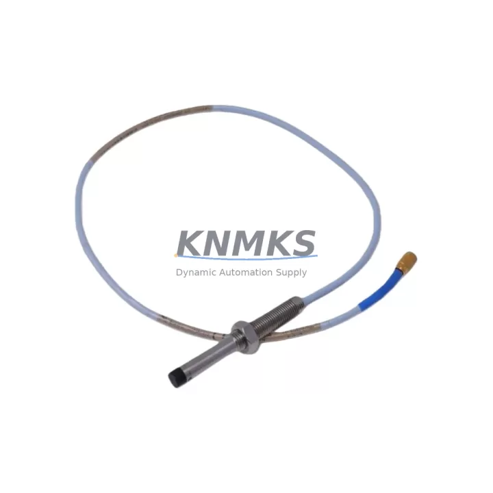
Bently Nevada 330102-20-55-10-02-CN Migration-Ready Proximity Probe for Legacy Control Systems
The Bently Nevada 330102-20-55-10-02-CN is an 8mm proximity probe from the 3300 XL Series, engineered for continuous vibration and position monitoring in rotating machinery. As legacy Bently Nevada 3300 and 7200 Series installations reach end-of-life, this probe serves as a verified migration-ready replacement that preserves signal chain integrity while enabling a controlled transition to modern condition monitoring architectures. Whether you are retrofitting a turbine protection panel, upgrading a compressor train monitoring rack, or restoring a decommissioned vibration channel, the 330102-20-55-10-02-CN delivers the dimensional and electrical compatibility required for a low-risk, minimum-downtime changeover.
This probe is designed to work within the complete 3300 XL proximity transducer system, which includes the matching extension cable (330130 Series) and the 3300 XL proximitor sensor (330180 Series). When replacing a failed or obsolete probe in an existing installation, engineers must verify that the total cable length — probe plus extension — matches the original system calibration. The 330102-20-55-10-02-CN has a 2.0-metre integral cable, and the system is typically completed with a 5.0-metre or 9.0-metre extension cable to reach the proximitor mounted on the rack. Mismatched cable lengths will shift the output voltage curve and require field recalibration of the 3300 XL proximitor or the Keyphasor module if one is present in the same rack.
For installations migrating from the older Bently Nevada 7200 Series probes, the 330102-20-55-10-02-CN provides a direct functional replacement when paired with the appropriate 3300 XL proximitor. The 7200 Series used a different gap voltage range and connector standard, so the transition requires updating the proximitor module, verifying the DCS or safety system input card scaling, and confirming that the vibration alarm setpoints in the System 1 or ADRE software reflect the new transducer sensitivity of 7.87 V/mm (200 mV/mil). This recalibration step is critical before returning the machine to service.
Migration Compatibility Table
| Parameter | 330102-20-55-10-02-CN | Legacy 7200 Series (Reference) |
|---|---|---|
| Probe Diameter | 8 mm | 8 mm |
| Integral Cable Length | 2.0 m | 0.9 m / 1.8 m |
| Sensitivity | 7.87 V/mm (200 mV/mil) | 7.87 V/mm (200 mV/mil) |
| Supply Voltage | -24 VDC (nom.) | -24 VDC (nom.) |
| Linear Range | 0.25 – 2.26 mm (10 – 89 mil) | 0.25 – 2.26 mm (10 – 89 mil) |
| Connector Type | 3300 XL standard (TNC) | 7200 Series (BNC) |
| Proximitor Compatibility | 330180 Series (3300 XL) | 7200 Series proximitor |
| Mounting Thread | M10 × 1 | M10 × 1 |
| Installation Clearance | Confirm bracket depth ≥ 35 mm | Same bracket, verify thread engagement |
| Retrofit Recommendation | Direct replacement with proximitor update | Replace probe + proximitor as a set |
| Commissioning Focus | Gap voltage, cable length, alarm scaling | Full recalibration required |
| Support terms | 12 Months | — |
Retrofit Planning for Existing Automation Systems
A successful retrofit begins with a complete audit of the existing transducer chain. Before removing the legacy probe, document the installed gap voltage (typically between -10.0 V and -12.0 V for a healthy 8mm probe at nominal gap), the proximitor output wiring termination at the 3300 rack I/O module, and the alarm trip setpoints configured in the turbine control system or safety instrumented system. If the machine is protected by a Bently Nevada 3500 Series rack, the I/O module card — such as the 3500/42M Proximitor/Seismic Monitor — must be confirmed compatible with the 3300 XL transducer system before the probe swap proceeds.
In control cabinets where space is constrained, verify that the new probe body and integral cable routing do not conflict with adjacent terminal blocks or cable trays. The 330102-20-55-10-02-CN uses a standard M10 × 1 mounting thread, so existing probe holders and brackets are typically reusable. However, if the original installation used a 7200 Series probe with a different bracket depth, a new probe holder may be required to achieve the correct gap setting of approximately 1.0 mm (40 mil) at the center of the linear range.
For systems where the 3300 XL proximitor (330180 Series) is already installed and in service, the probe replacement is straightforward: disconnect the extension cable at the proximitor, remove the old probe, install the 330102-20-55-10-02-CN, reconnect the 330130 Series extension cable, and verify the gap voltage before re-enabling the channel. If the installation also includes a Keyphasor transducer on the same shaft, confirm that the Keyphasor module in the rack is not affected by the channel bypass during the swap. In multi-channel racks, adjacent channels monitoring the same machine train should remain active throughout the procedure to maintain continuous protection on the other measurement planes.
Where the retrofit involves a broader system upgrade — for example, migrating from a standalone 3300 rack to a fully integrated 3500 Series protection system — additional components will be required. The 3500/15 Power Supply module, the 3500/20 Rack Interface Module, and the appropriate 3500/42M or 3500/40M I/O cards must be sized and configured before the new probe is commissioned. Communication links to the DCS via Modbus RTU or the 3500/92 Communication Gateway should be verified at the protocol level, and the System 1 software database should be updated to reflect the new transducer serial numbers and calibration records.
Downtime Control During System Migration
Minimizing unplanned downtime during a proximity probe replacement requires a structured pre-outage preparation process. Before the maintenance window opens, the replacement 330102-20-55-10-02-CN should be bench-tested using a portable proximitor or a calibration fixture to confirm that the output voltage at a known gap distance matches the expected sensitivity curve. This pre-shipment functional test, which is performed on every unit before dispatch, reduces the risk of discovering a defective component after the machine has already been taken offline.
During the outage, the recommended sequence is: isolate the vibration channel at the rack, bypass the trip function in the safety system or turbine control system, remove the legacy probe, install the new probe and verify the gap mechanically, reconnect the extension cable, restore the channel, and confirm the live gap voltage reading before re-enabling the trip. This sequence protects the original program logic in the turbine control system and prevents a spurious trip from interrupting the restart sequence. If the machine uses a redundant protection architecture with two probes per measurement plane (X and Y), the second probe channel remains active throughout the single-probe replacement, maintaining continuous radial vibration monitoring.
For planned turnaround projects where multiple probes are being replaced across a machine train, a staged replacement approach — replacing one probe per shift while keeping adjacent channels live — is strongly recommended. This approach limits the exposure window for each measurement plane and allows the maintenance team to verify each channel before moving to the next. All gap voltage readings, extension cable serial numbers, and proximitor output values should be recorded in the maintenance management system to support future calibration audits and spare parts lifecycle planning.
Retrofit Support FAQ
Q: Is the 330102-20-55-10-02-CN a direct drop-in replacement for the 330102-20-55-10-02?
A: Yes. The -CN suffix designates the connector variant for the Chinese market distribution channel. The probe body, cable length, sensitivity, and electrical specifications are identical to the standard 330102-20-55-10-02. It is fully compatible with the 330130 Series extension cable and the 330180 Series 3300 XL proximitor.
Q: What commissioning checks are required after installation?
A: After installing the probe and reconnecting the extension cable, measure the gap voltage at the proximitor output with the shaft stationary. The reading should be between -10.0 V and -12.0 V for a nominal 1.0 mm (40 mil) gap. If the reading is outside this range, adjust the probe gap mechanically until the correct voltage is achieved. Then verify the vibration channel output (0 V at rest) and confirm that the alarm and trip setpoints in the protection rack or DCS are correctly scaled for a 7.87 V/mm sensitivity.
Q: Can this probe be used with a Bently Nevada 3500 Series rack?
A: Yes, when used as part of the complete 3300 XL transducer system (probe + extension cable + 330180 proximitor), the output is compatible with the 3500/42M Proximitor/Seismic Monitor I/O module. Confirm the I/O module configuration in the 3500 Rack Configuration Software matches the transducer type and sensitivity before enabling the channel.
Q: What is the support terms and supply lead time?
A: Every unit is covered by a support terms confirmed by quotation from the date of shipment. Stock is maintained for immediate dispatch. For volume orders or long-term supply agreements supporting planned maintenance schedules, contact our sales team to discuss inventory reservation and consignment options.
© 2026 KNMKS. All rights reserved.
Original Source: https://knmks.com
Contact: admin@knmks.com | +86 18359268345
Product Identification
- Brand / Ecosystem
-
Bently Nevada
Bently Nevada - Model / Series
-
330102-20-55-10-02-CN
Bently Nevada 3300 XL / 3301 Series - Product Family
- Sensors
- Availability Status
- Available on request after model and quantity confirmation
- Inquiry Type
- B2B RFQ, replacement inquiry and project spare-part request
- Pre-Quote Check
- Exact SKU, brand, series, quantity, nameplate photos and destination country are checked before quotation
System Path
Where this product fits in the KNMKS automation structure.
Specification & Inquiry Focus
- Sensor range
- Photoelectric, proximity and process sensors
- Common needs
- Output type, distance and connector
- Project support
- Machine detection and replacement inquiry
Buyer Confirmation
Information KNMKS checks before replying.
- Exact model
- 330102-20-55-10-02-CN
- Brand / ecosystem
- Bently Nevada
- Product family
- Sensors
- Application note
- Replacement, maintenance, project build or spare-part list
- Useful photos
- Nameplate, installed unit, cabinet layout or connector side
- Delivery details
- Quantity, destination country and target schedule
Document Support
Files and notes can be confirmed during quotation.
- Product photos or nameplate confirmation when available
- Packing and delivery notes before quotation confirmation
- Support scope and delivery terms confirmed per inquiry
- Export document coordination for qualified B2B requests
Inquiry Support
- NPN/PNP, analog and digital output checking
- Connector and cable compatibility review
- Fast inquiry support for maintenance teams
What to Send Us
- Brand and exact model number: Bently Nevada 330102-20-55-10-02-CN
- Quantity and required delivery time
- Application, replacement requirement or nameplate photo
- Destination country and shipping preference
RFQ Preparation
This is a product inquiry page built for RFQ communication.
Fast Model Check
Send this model to KNMKS for confirmation.
Include quantity, destination country and photos if this is a maintenance replacement. The inquiry will be saved with a reference number after submission.
Brand & Compatibility Note
KNMKS displays automation product information for well-known industrial brand ecosystems and compatible replacement references. Brand names are used for product identification and compatibility reference only; final availability and commercial terms are confirmed per quotation.
 Manufacturing
 Machine Tools
 Packaging
 Energy & Power



 PLCs & Controllers
 HMI & Displays
 Servo Systems
 Variable Frequency Drives