
Overview
Bently Nevada 330102-00-16-10-02-00 Migration-Ready 3300 XL Probe: Legacy System Retrofit and Compatibility Upgrade
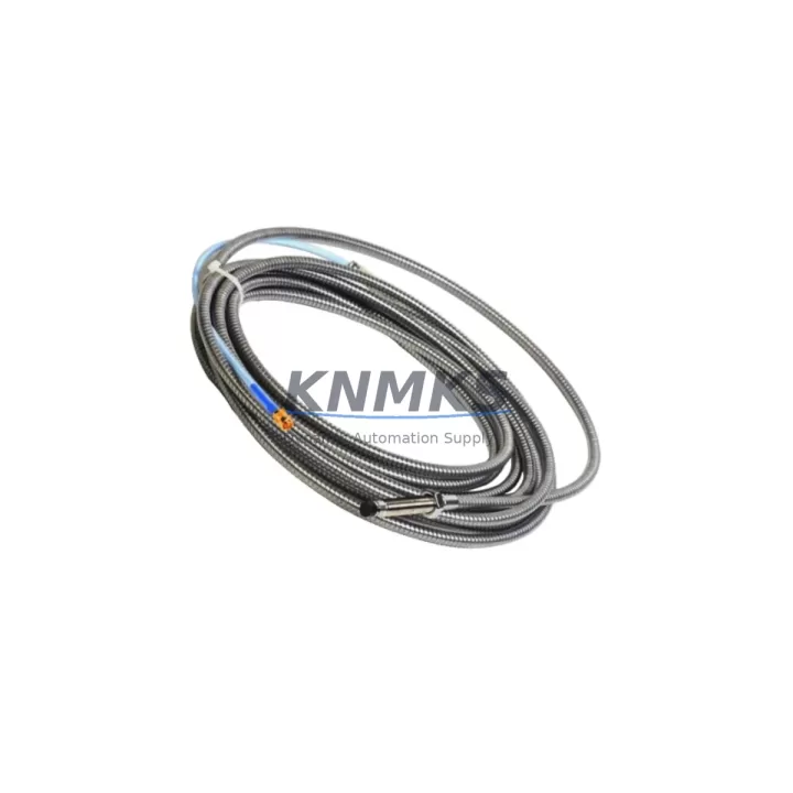
The Bently Nevada 330102-00-16-10-02-00 is an 8mm eddy current proximity probe engineered for direct replacement and migration within the 3300 XL Series machinery protection platform. As industrial facilities face increasing pressure to extend the operational life of legacy vibration monitoring systems, this probe delivers a verified drop-in solution that eliminates the need for full system overhaul. Whether you are replacing a failed sensor on a critical rotating machine or executing a planned upgrade of an aging 3300 Series installation, the 330102-00-16-10-02-00 provides the dimensional accuracy, signal conditioning compatibility, and field-proven reliability required for uninterrupted plant operations.
Designed to interface directly with the Bently Nevada 3300 XL proximitor/extension cable assemblies, this probe maintains the standard 5-metre system length configuration when paired with a compatible 330130 or 330180 series extension cable. Engineers migrating from earlier 3300 Series probes — including the 330101 and 330103 families — will find that the 330102-00-16-10-02-00 preserves the original signal output range of 0 to -24 VDC, ensuring that existing 3500/40M or 3500/42M monitor cards continue to receive correctly scaled vibration and position data without requiring recalibration of alarm and danger setpoints.
During retrofit planning, it is essential to verify the power supply capacity of the existing proximitor enclosure or junction box. The 330102-00-16-10-02-00 operates on a -24 VDC supply and draws current consistent with the standard 3300 XL probe specification; however, aging power distribution modules within legacy control cabinets may exhibit voltage droop under multi-channel load. Confirming that the 3300 XL power supply module — or its replacement equivalent — can sustain stable output across all active probe channels is a prerequisite before commissioning the new sensor.
Terminal wiring compatibility is another critical checkpoint. The probe cable terminates in a standard Bently Nevada connector that mates with the 330130 extension cable’s field-end connector. When the existing extension cable shows signs of insulation degradation or connector wear, simultaneous replacement with a new 330130-045-00-00 or 330180-045-00-00 extension cable is strongly recommended to avoid intermittent signal faults that can trigger nuisance trips on the 3500 Series monitor rack. Technicians should also inspect the proximitor housing for moisture ingress, particularly in installations where the probe is mounted in a high-humidity or wash-down environment.
Backplane and rack interface considerations apply when the 330102-00-16-10-02-00 is used within a 3500 Series rack alongside other I/O modules. The 3500/40M and 3500/42M monitor cards accept the probe’s output directly via the I/O module terminal block; no additional signal conditioning is required. However, if the facility is migrating from a legacy 3300 Series standalone monitor to a full 3500 rack-based system, the module address configuration within the rack must be verified against the existing DCS or safety system tag database. Incorrect slot addressing can result in mismatched channel assignments in the historian or DCS faceplate, requiring HMI screen updates to realign tag names, engineering units, and alarm thresholds.
Program compatibility is a frequent concern during probe replacement on machines monitored by a Bently Nevada System 1 or System 1 Evolution condition monitoring platform. Because the 330102-00-16-10-02-00 maintains the same sensitivity specification (7.87 V/mm or 200 mV/mil), no changes to the System 1 database configuration are required when performing a like-for-like replacement. This preserves the integrity of trend data continuity and avoids the need to re-baseline vibration signatures after the swap.
Communication link integrity between the 3500 rack and the plant DCS or safety instrumented system should be validated as part of the post-installation verification. Where the 3500 rack communicates via a 3500/92 or 3500/93 communication gateway module, the Modbus or Ethernet/IP data map should be verified to confirm that the replaced channel continues to report correctly to the upstream control system. Any changes to rack slot configuration during the migration may shift the Modbus register map, requiring a coordinated update with the DCS engineering team.
Installation space confirmation is straightforward for the 330102-00-16-10-02-00, as its 8mm probe body and standard thread (M10 x 1) are dimensionally identical to the probes it replaces. Bracket and holder assemblies designed for the original 3300 XL probe require no modification. The probe tip-to-target gap should be set to the midpoint of the linear range — typically 1.0 to 1.5 mm for a steel target — using a calibrated gap voltage measurement at the proximitor output before the machine is returned to service.
Firmware version compatibility is not a concern for the probe itself, as the 330102-00-16-10-02-00 is a passive transducer. However, if the associated 3500/40M or 3500/42M monitor card firmware is below a minimum supported revision, certain advanced features such as dynamic pressure measurement or vector filtering may not function as expected. Verifying the monitor card firmware version against the current Bently Nevada release notes prior to installation is a recommended best practice, particularly for facilities that have not performed a rack firmware update in several years.
Field commissioning of the 330102-00-16-10-02-00 follows the standard Bently Nevada probe installation procedure: install the probe in the holder, set the gap voltage, verify the output at the proximitor test point, confirm the signal at the monitor card channel, and check the alarm relay status in the 3500 rack display. Each unit supplied by KNMKS undergoes pre-shipment functional testing to verify gap voltage output, sensitivity linearity, and connector integrity, reducing on-site commissioning time and minimizing the risk of installation-related faults.
Migration Compatibility Table
| Parameter | 330102-00-16-10-02-00 | Legacy 330101 / 330103 | Notes |
|---|---|---|---|
| Probe Diameter | 8 mm | 8 mm | Direct dimensional fit; no bracket modification required |
| Thread Size | M10 x 1 | M10 x 1 | Compatible with existing probe holders |
| System Length | 5 m (standard) | 5 m (standard) | Pair with 330130 or 330180 extension cable |
| Supply Voltage | -24 VDC | -24 VDC | Verify power supply output stability under full channel load |
| Output Range | 0 to -24 VDC | 0 to -24 VDC | No monitor card recalibration required |
| Sensitivity | 7.87 V/mm (200 mV/mil) | 7.87 V/mm (200 mV/mil) | System 1 database configuration unchanged |
| Monitor Compatibility | 3500/40M, 3500/42M | 3300 standalone, 3500 rack | Verify slot address and DCS tag mapping if migrating to 3500 rack |
| Communication Protocol | Modbus / Ethernet/IP (via 3500/92-93) | Modbus (via legacy gateway) | Validate register map after rack reconfiguration |
| Installation Space | Standard 8mm probe envelope | Standard 8mm probe envelope | No mechanical modification required |
| Firmware Dependency | None (passive transducer) | None | Verify monitor card firmware if advanced features are required |
| Pre-Shipment Testing | Yes — gap voltage, sensitivity, connector | Varies by supplier | KNMKS functional test included |
| Support terms | 12 Months | N/A (legacy/discontinued) | Covers manufacturing defects and signal performance |
Retrofit Planning for Existing Automation Systems
A successful retrofit of the 330102-00-16-10-02-00 into an existing machinery protection system requires a structured review of all interdependent components within the measurement chain. The probe does not operate in isolation — its performance depends on the condition and compatibility of the full system, from the proximitor housing at the machine to the monitor card in the control room rack.
Begin by auditing the extension cable. The 330130-045-00-00 armored extension cable is the standard pairing for this probe in most turbine and compressor applications. If the existing cable shows jacket cracking, connector corrosion, or insulation resistance below specification, replacement before probe installation prevents signal noise that could be misattributed to the new probe. In high-vibration environments, consider upgrading to the 330180 series armored cable for additional mechanical protection.
The proximitor — typically a 3300 XL 8mm proximitor such as the 330180-X1-05 — should be inspected for output voltage stability and housing seal integrity. A degraded proximitor will produce erratic gap voltage readings even with a new probe installed, leading to unnecessary troubleshooting cycles. Where the proximitor is also at end of life, simultaneous replacement with the probe reduces total installation downtime.
Within the 3500 rack, the I/O module terminal block connections for the affected channel should be cleaned and re-torqued to specification. Loose terminal connections are a common source of intermittent alarms following probe replacement and are easily addressed during the planned outage window. If the rack also houses a 3500/20 power supply module that has not been serviced recently, verifying its output voltage under load is a prudent step before returning the machine to service.
For facilities integrating the 3500 rack with a modern DCS via a 3500/92 Ethernet communication module, the channel data map should be exported and archived before any rack reconfiguration. This provides a rollback reference if the post-migration DCS tag verification reveals discrepancies. HMI faceplate screens displaying vibration trend data for the affected machine should be reviewed by the control systems team to confirm that engineering unit scaling and alarm setpoint displays remain accurate after the probe swap.
Where the retrofit scope extends beyond a single probe replacement to include I/O expansion or the addition of new measurement points, a Bently Nevada 3500/25 keyphasor module or a 3500/50M tachometer input module may be required to support additional speed reference channels. Planning for these additions during the initial outage avoids a second planned shutdown for incremental scope additions.
Downtime Control During System Migration
Minimizing unplanned downtime during probe replacement requires preparation that begins well before the machine is taken offline. The 330102-00-16-10-02-00 is stocked by KNMKS for immediate dispatch, eliminating the lead time uncertainty associated with OEM procurement channels for legacy components. Having the replacement probe, extension cable, and any required connector tools on-site before the maintenance window opens is the single most effective measure for controlling outage duration.
Before isolating the measurement channel, document the existing gap voltage reading at the proximitor test point and record the vibration and position values displayed on the 3500 monitor card. These baseline values serve as the acceptance criteria for the post-installation verification and allow the commissioning technician to confirm that the new probe is correctly gapped and performing within specification before the machine is restarted.
The original program logic in the 3500 monitor card — including alarm setpoints, time delays, and relay output assignments — does not require modification for a like-for-like probe replacement. This preserves the integrity of the machinery protection function throughout the maintenance activity and eliminates the risk of inadvertently altering protection parameters during the outage. The System 1 or System 1 Evolution historian will continue to record data on the same tag without requiring a database update, maintaining trend data continuity across the replacement event.
For facilities operating under a safety instrumented system that receives a hardwired trip signal from the 3500 rack, the SIS bypass procedure should be activated for the affected channel before probe removal and deactivated only after the post-installation verification is complete and the gap voltage has been verified. This prevents a spurious trip from propagating to the SIS during the brief period when the measurement channel is open-circuit.
Post-installation, a 30-minute observation period at reduced load before returning the machine to full operating speed allows the commissioning team to confirm signal stability, verify that no nuisance alarms are active, and validate that the DCS and historian are receiving clean data from the replaced channel. This structured approach to commissioning reduces the risk of a repeat outage caused by installation-related issues that were not detected during the initial verification.
Retrofit Support FAQ
Q: Is the 330102-00-16-10-02-00 a direct replacement for the 330101-00-16-10-02-00?
A: Yes. The 330102 series supersedes the 330101 series for 8mm 3300 XL system applications. The probe body dimensions, thread specification, system length, supply voltage, and output sensitivity are identical, allowing direct substitution without modification to the probe holder, extension cable, or monitor card configuration. KNMKS supplies both series and can confirm the correct replacement SKU for your specific installation upon request.
Q: What commissioning steps are required after installing the 330102-00-16-10-02-00?
A: Set the probe-to-target gap to achieve a gap voltage of approximately -10 to -12 VDC at the proximitor output (midpoint of the linear range for a steel target). Verify the output at the 3500 monitor card channel display, confirm that the vibration and position readings are within expected operating range, and check that no alarm or danger relays are active. Document the as-left gap voltage for the maintenance record. The full commissioning procedure is detailed in the Bently Nevada 3300 XL Installation Manual.
Q: Does KNMKS perform pre-shipment testing on the 330102-00-16-10-02-00?
A: Yes. Each unit undergoes functional testing prior to dispatch, including gap voltage output verification, sensitivity linearity check, and connector integrity inspection. A test report is available upon request. Units are shipped with protective packaging to prevent connector damage in transit. KNMKS maintains stock inventory for immediate dispatch, with global shipping to support planned and emergency maintenance requirements.
Q: What support terms coverage applies to the 330102-00-16-10-02-00 supplied by KNMKS?
A: All units are covered by a support terms confirmed by quotation from the date of shipment, covering manufacturing defects and signal performance deviations from specification. Support requests are supported by KNMKS technical staff, who can assist with fault diagnosis, replacement dispatch, and installation guidance. For support terms service or technical support, contact admin@knmks.com or +86 18359268345.
© 2026 KNMKS. All rights reserved.
Original Source: https://knmks.com
Contact: admin@knmks.com | +86 18359268345
Product Identification
- Brand / Ecosystem
-
Bently Nevada
Bently Nevada - Model / Series
-
330102-00-16-10-02-00
Bently Nevada 3300 XL / 3301 Series - Product Family
- Sensors
- Availability Status
- Available on request after model and quantity confirmation
- Inquiry Type
- B2B RFQ, replacement inquiry and project spare-part request
- Pre-Quote Check
- Exact SKU, brand, series, quantity, nameplate photos and destination country are checked before quotation
System Path
Where this product fits in the KNMKS automation structure.
Specification & Inquiry Focus
- Sensor range
- Photoelectric, proximity and process sensors
- Common needs
- Output type, distance and connector
- Project support
- Machine detection and replacement inquiry
Buyer Confirmation
Information KNMKS checks before replying.
- Exact model
- 330102-00-16-10-02-00
- Brand / ecosystem
- Bently Nevada
- Product family
- Sensors
- Application note
- Replacement, maintenance, project build or spare-part list
- Useful photos
- Nameplate, installed unit, cabinet layout or connector side
- Delivery details
- Quantity, destination country and target schedule
Document Support
Files and notes can be confirmed during quotation.
- Product photos or nameplate confirmation when available
- Packing and delivery notes before quotation confirmation
- Support scope and delivery terms confirmed per inquiry
- Export document coordination for qualified B2B requests
Inquiry Support
- NPN/PNP, analog and digital output checking
- Connector and cable compatibility review
- Fast inquiry support for maintenance teams
What to Send Us
- Brand and exact model number: Bently Nevada 330102-00-16-10-02-00
- Quantity and required delivery time
- Application, replacement requirement or nameplate photo
- Destination country and shipping preference
RFQ Preparation
This is a product inquiry page built for RFQ communication.
Fast Model Check
Send this model to KNMKS for confirmation.
Include quantity, destination country and photos if this is a maintenance replacement. The inquiry will be saved with a reference number after submission.
Brand & Compatibility Note
KNMKS displays automation product information for well-known industrial brand ecosystems and compatible replacement references. Brand names are used for product identification and compatibility reference only; final availability and commercial terms are confirmed per quotation.
 Manufacturing
 Machine Tools
 Packaging
 Energy & Power



 PLCs & Controllers
 HMI & Displays
 Servo Systems
 Variable Frequency Drives