
Overview
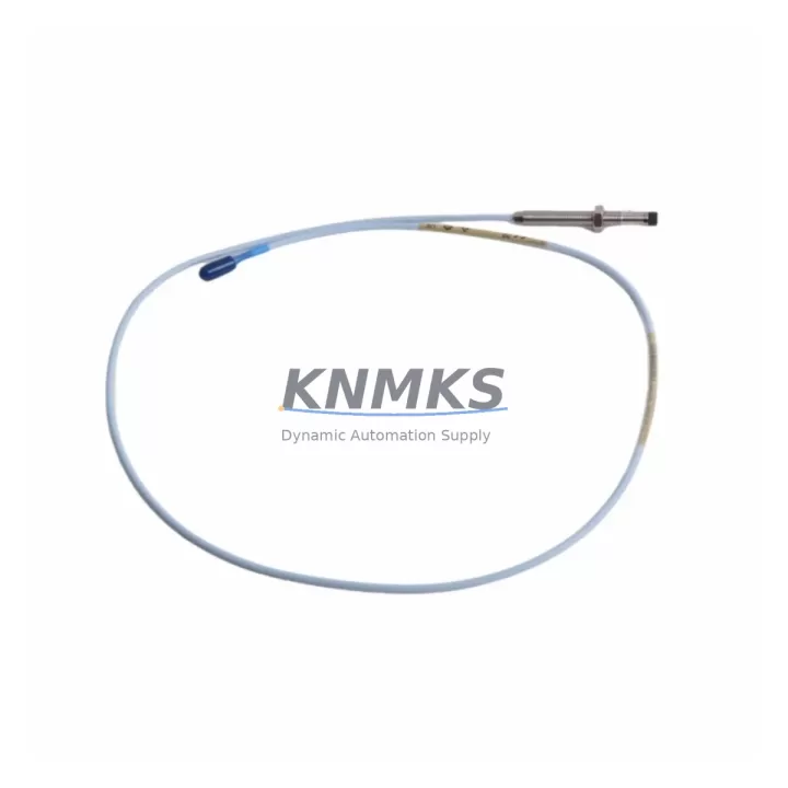
Bently Nevada 330101-48-71-20-02-05 Migration-Ready Proximity Transducer: Legacy System Retrofit & Upgrade
The Bently Nevada 330101-48-71-20-02-05 is an 8mm eddy-current proximity transducer engineered for the 3300 XL Series vibration monitoring platform. As aging distributed control systems and condition monitoring networks approach end-of-life, this transducer serves as a direct, migration-ready replacement for discontinued 330100-series probes, enabling maintenance teams to restore full shaft vibration and position measurement capability without redesigning the existing signal chain or replacing the 3300 XL monitor rack.
For facilities running legacy turbomachinery protection systems — including steam turbines, gas compressors, centrifugal pumps, and gearboxes — the 330101-48-71-20-02-05 provides a validated retrofit path that preserves original wiring topology, terminal block assignments, and monitor calibration constants. The probe’s 48-inch (1,219 mm) integral cable length, 20-mil (0.508 mm) linear range, and -02 connector configuration are factory-matched to the 3300 XL proximitor/extension cable system, eliminating the need for field-level signal recalibration in most direct-swap scenarios.
Before committing to a retrofit, engineers should verify the following parameters against the existing installation: supply voltage at the proximitor input (typically –24 VDC from the 3300 XL power supply module), terminal block wiring polarity at the I/O termination panel, gap voltage at the installed probe tip (target –10 VDC at nominal air gap), and the shield grounding scheme used in the original cable run. Where the original 330100-series probe used a different cable jacket or conduit fitting, the 330101-48-71-20-02-05’s -05 armor designation should be confirmed against the conduit entry size in the junction box or machinery guard.
In multi-channel monitor configurations, the 3300 XL rack may house companion modules such as the 3300/16 dual-channel monitor card or the 3300/55 position monitor. When replacing probes across multiple measurement planes simultaneously, it is advisable to document each channel’s existing gap voltage and phase reference before removal, then restore and verify each channel independently after installation. This approach protects the integrity of the overall machinery protection logic and avoids nuisance trips during the commissioning window.
For systems where the original Keyphasor signal is routed through a 3300/25 Keyphasor module, the replacement transducer installation should include verification of the once-per-revolution trigger level and hysteresis settings within the monitor configuration software. Similarly, if the plant’s DCS or safety instrumented system receives 4–20 mA retransmission outputs from the 3300 XL rack, those analog output scaling parameters should be confirmed unchanged after the probe swap to prevent false alarms at the control room level.
Communication protocol migration is another consideration for facilities transitioning from standalone 3300 XL racks to integrated asset management platforms. The 330101-48-71-20-02-05 is fully compatible with 3300 XL monitors that communicate via the System 1 condition monitoring software over RS-232/RS-485 serial links, as well as newer installations using Ethernet-based System 1 Evolution. No firmware update to the monitor card is required solely for a probe replacement, though it is good practice to confirm the monitor firmware revision is current before returning the machine to service.
Installation space constraints are common in retrofit projects. The 330101-48-71-20-02-05’s 8mm probe body diameter and standard M10 x 1 thread allow it to fit existing probe holders and armored conduit runs without modification in the vast majority of 3300 XL installations. Where the original probe was secured with a locknut and jam nut arrangement, the same hardware can be reused, provided the threads are inspected and cleaned before reinstallation.
All units supplied by KNMKS are tested prior to shipment, with gap voltage linearity verified across the full measurement range. Each transducer ships with a test report confirming output sensitivity (nominally –200 mV/mil or –7.87 V/mm) and is covered by a support terms confirmed by quotation against manufacturing defects. In-stock inventory is maintained to support urgent maintenance windows and unplanned outages, with same-day dispatch available for orders confirmed before the daily cutoff.
Migration Compatibility Table
| Parameter | 330101-48-71-20-02-05 (This Unit) | Legacy 330100-Series Reference | Retrofit Notes |
|---|---|---|---|
| Probe Diameter | 8 mm | 8 mm | Direct fit; no probe holder modification required |
| Thread Size | M10 x 1 | M10 x 1 | Existing locknut and jam nut hardware reusable |
| Cable Length | 48 in (1,219 mm) | Varies (check original BOM) | Confirm extension cable length to proximitor matches total system requirement |
| Linear Range | 20 mil (0.508 mm) | 20 mil | Gap voltage target: –10 VDC at nominal air gap |
| Supply Voltage | –24 VDC (from 3300 XL power supply) | –24 VDC | Verify power supply module output before installation |
| Output Sensitivity | –200 mV/mil (–7.87 V/mm) | –200 mV/mil | No monitor recalibration required for direct swap |
| Connector Type | -02 (standard 3300 XL) | -02 | Compatible with standard 3300 XL extension cables |
| Armor / Jacket | -05 (armored) | Varies | Confirm conduit entry size at junction box |
| Communication Compatibility | System 1 / System 1 Evolution (RS-232, RS-485, Ethernet) | System 1 (RS-232/RS-485) | No firmware update required for probe swap |
| Monitor Compatibility | 3300 XL (3300/16, 3300/25, 3300/55) | 3300 XL series | Verify monitor firmware revision before return to service |
| Support terms | 12 months from date of shipment — covers manufacturing defects; includes pre-shipment test report | ||
Retrofit Planning for Existing Automation Systems
A successful retrofit begins well before the maintenance window opens. For 3300 XL-based machinery protection systems, the bill of materials for a complete probe replacement typically extends beyond the transducer itself. The 330101-48-71-20-02-05 is designed to work within the existing signal chain, but the surrounding components must be assessed for condition and compatibility.
The proximitor — often a 3300 XL 8mm proximitor/extension cable assembly — converts the probe’s high-frequency oscillator signal into the DC voltage that the monitor card reads. If the proximitor has been in service for more than ten years or shows signs of connector corrosion, replacing it alongside the probe during the same maintenance window eliminates a common source of intermittent faults after the probe swap. Extension cable condition should also be inspected: damaged shielding or cracked jacket insulation can introduce noise that mimics shaft vibration, leading to false alarms on the 3300/16 dual-channel monitor card.
Power distribution within the 3300 XL rack is supplied by a dedicated power supply module. Before the retrofit, confirm that the power supply’s output voltage is within specification and that the rack’s total current draw — including any newly added I/O modules or communication cards — remains within the power supply’s rated capacity. If the rack has been expanded since original commissioning, a power budget review is advisable.
For plants that have added a 3300/55 position monitor or a 3300/25 Keyphasor module to the original rack configuration, the probe replacement plan should include a channel-by-channel verification of all monitor setpoints, including alert and danger thresholds, time delays, and voting logic. These parameters are stored in the monitor’s non-volatile memory and are not affected by a probe swap, but confirming them before and after the work provides a documented baseline for the post-maintenance functional test.
Where the control system includes a signal isolator or barrier between the 3300 XL rack and a DCS analog input card, the isolator’s input impedance and loop power characteristics should be verified against the proximitor’s output specification. Zener barrier or galvanic isolator selection affects the DC output range available to the DCS, and an incompatible isolator can clip the signal at high vibration amplitudes — a failure mode that is easy to miss during a bench test but becomes apparent only under full operating conditions.
Finally, if the plant uses a programming cable or laptop-based configuration tool to access the 3300 XL monitor’s internal settings, ensure that the configuration file is backed up before the maintenance window begins. This protects against accidental parameter loss and provides a reference for the post-installation verification checklist.
Downtime Control During System Migration
Minimizing unplanned downtime is the primary driver behind stocking migration-ready replacement parts such as the 330101-48-71-20-02-05. When a proximity transducer fails on a critical rotating machine, the time between fault detection and return to service is determined almost entirely by parts availability and the efficiency of the swap procedure.
Pre-staging the replacement transducer, extension cable, and any associated hardware before the machine is taken offline compresses the actual maintenance window to the time required for mechanical removal, installation, gap setting, and functional verification — typically two to four hours for a single-channel replacement on an accessible probe location. For multi-plane replacements or installations in confined spaces, additional time should be budgeted for cable routing and connector inspection.
Protecting the original program logic in the 3300 XL monitor is straightforward: the monitor’s configuration is stored in non-volatile memory and is not affected by removing power to the probe circuit. However, if the rack must be de-energized for safety reasons during the probe swap, the monitor will perform a self-test on power-up and will not generate spurious trip outputs during the startup sequence, provided the bypass/inhibit function is activated before de-energization and released only after the gap voltage has been verified within the acceptable range.
Maintaining field control continuity during the swap is possible in redundant monitoring configurations where a second measurement plane or a redundant monitor channel remains active. In single-channel installations, the machine must be taken offline, but the duration of the outage can be minimized by having a trained technician on-site with the replacement unit, a calibrated gap-setting tool, and a copy of the original installation record showing the nominal air gap dimension for the specific shaft material and surface finish.
Post-installation, the functional verification sequence should confirm gap voltage at the monitor’s front-panel meter or via the System 1 software interface, check for alarm and danger setpoint integrity, and perform a brief run-up observation to confirm that the vibration trend is consistent with the pre-fault baseline. This sequence, when documented, also satisfies most plant quality management system requirements for maintenance records on safety-critical instrumentation.
Retrofit Support FAQ
Q: Is the 330101-48-71-20-02-05 a direct replacement for the discontinued 330100-48-71-20-02-05?
A: Yes. The 330101 series was introduced as the direct successor to the 330100 series, with identical mechanical dimensions, thread specification, cable length, and electrical output characteristics. In the vast majority of 3300 XL installations, the swap is drop-in with no wiring or calibration changes required. Confirm the connector type (-02) and armor designation (-05) match the original installation record before ordering.
Q: What pre-shipment testing is performed, and what documentation is included?
A: Every unit undergoes gap voltage linearity testing across the full 20-mil measurement range before dispatch. A test report confirming output sensitivity (–200 mV/mil) and linearity is included with each shipment. Units are shipped in anti-static packaging with connector caps installed to protect the probe tip and cable termination during transit.
Q: How do I verify wiring compatibility with my existing 3300 XL termination panel?
A: The 330101-48-71-20-02-05 uses the standard Bently Nevada three-wire connection (shield, center conductor, and outer conductor) compatible with all 3300 XL I/O termination panels. Refer to the original installation drawing for terminal block assignments. If the original drawing is unavailable, the 3300 XL system manual (document 141078-01) provides the standard wiring diagram for 8mm probe installations.
Q: What is the support terms coverage, and what is the typical lead time from stock?
A: All units supplied by KNMKS carry a support terms confirmed by quotation from the date of shipment, covering manufacturing defects in materials and workmanship. In-stock units are dispatched same day for orders confirmed before the daily cutoff. For urgent maintenance requirements, contact the sales team directly to confirm real-time inventory availability and expedited shipping options.
© 2026 KNMKS. All rights reserved.
Original Source: https://knmks.com
Contact: admin@knmks.com | +86 18359268345
Product Identification
- Brand / Ecosystem
-
Bently Nevada
Bently Nevada - Model / Series
-
330101-48-71-20-02-05
Bently Nevada 3300 XL / 3301 Series - Product Family
- Sensors
- Availability Status
- Available on request after model and quantity confirmation
- Inquiry Type
- B2B RFQ, replacement inquiry and project spare-part request
- Pre-Quote Check
- Exact SKU, brand, series, quantity, nameplate photos and destination country are checked before quotation
System Path
Where this product fits in the KNMKS automation structure.
Specification & Inquiry Focus
- Sensor range
- Photoelectric, proximity and process sensors
- Common needs
- Output type, distance and connector
- Project support
- Machine detection and replacement inquiry
Buyer Confirmation
Information KNMKS checks before replying.
- Exact model
- 330101-48-71-20-02-05
- Brand / ecosystem
- Bently Nevada
- Product family
- Sensors
- Application note
- Replacement, maintenance, project build or spare-part list
- Useful photos
- Nameplate, installed unit, cabinet layout or connector side
- Delivery details
- Quantity, destination country and target schedule
Document Support
Files and notes can be confirmed during quotation.
- Product photos or nameplate confirmation when available
- Packing and delivery notes before quotation confirmation
- Support scope and delivery terms confirmed per inquiry
- Export document coordination for qualified B2B requests
Inquiry Support
- NPN/PNP, analog and digital output checking
- Connector and cable compatibility review
- Fast inquiry support for maintenance teams
What to Send Us
- Brand and exact model number: Bently Nevada 330101-48-71-20-02-05
- Quantity and required delivery time
- Application, replacement requirement or nameplate photo
- Destination country and shipping preference
RFQ Preparation
This is a product inquiry page built for RFQ communication.
Fast Model Check
Send this model to KNMKS for confirmation.
Include quantity, destination country and photos if this is a maintenance replacement. The inquiry will be saved with a reference number after submission.
Brand & Compatibility Note
KNMKS displays automation product information for well-known industrial brand ecosystems and compatible replacement references. Brand names are used for product identification and compatibility reference only; final availability and commercial terms are confirmed per quotation.
 Manufacturing
 Machine Tools
 Packaging
 Energy & Power



 PLCs & Controllers
 HMI & Displays
 Servo Systems
 Variable Frequency Drives