
Overview
Bently Nevada 330101-33-52-10-12-05 Migration-Ready Proximity Probe for Legacy Control Systems
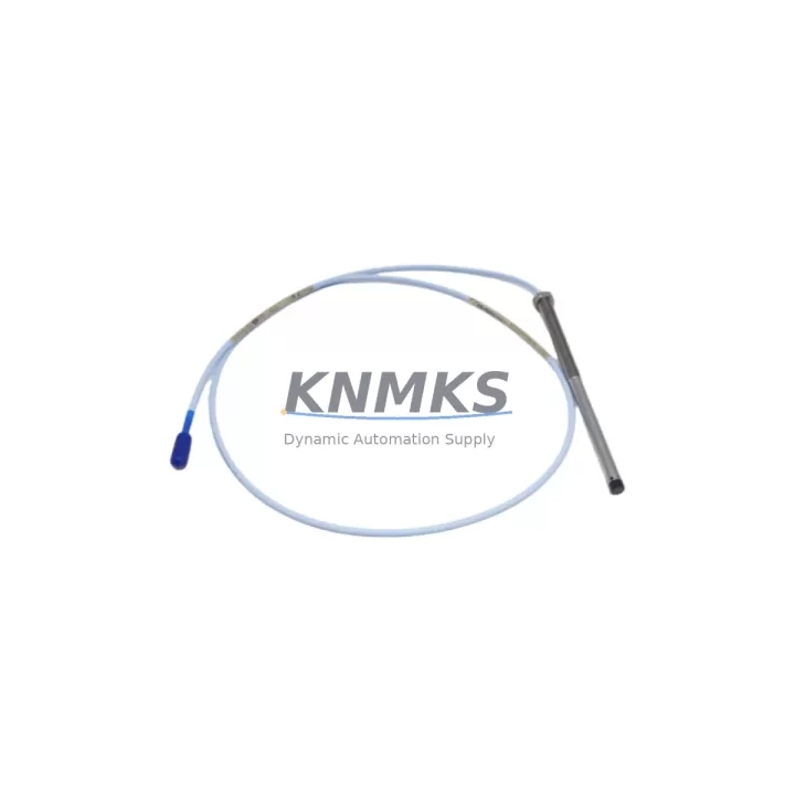
The Bently Nevada 330101-33-52-10-12-05 is an 8mm eddy-current proximity probe with a 52-inch (1.3 m) integral cable, designed for the 3300 XL Proximity Transducer System. This unit serves as a direct, migration-ready replacement for legacy vibration monitoring installations where the original probe has reached end-of-life, been discontinued, or is no longer available through standard OEM channels. Whether you are restoring a turbine protection loop, upgrading a compressor train monitoring rack, or consolidating spare-parts inventory for a long-running plant, this probe delivers verified electrical and mechanical compatibility with existing 3300 XL monitor cards and field wiring without requiring program changes or signal recalibration.
Each unit ships fully tested against Bently Nevada gap voltage, sensitivity, and frequency response specifications. The 8mm tip geometry and standard Bently Nevada thread pattern allow direct installation into existing probe holders and brackets, eliminating the need to modify machinery or re-machine probe bosses. The 52-inch cable length matches the most common field-installed configuration, reducing the risk of wiring shortfalls during swap-out. A support terms confirmed by quotation cover all units against manufacturing defects and out-of-specification performance from the date of shipment.
Migration Compatibility Table
| Parameter | 330101-33-52-10-12-05 (This Unit) | Legacy / Replaced Models | Notes |
|---|---|---|---|
| Probe Diameter | 8 mm | 8 mm (330101 series) | Direct mechanical fit; no re-machining required |
| Cable Length | 52 in (1.3 m) | 52 in standard field config | Verify total system cable length with extension cable |
| System Compatibility | 3300 XL Monitor Series | 3300 NSv, 3300/16, 3300/20 | Confirm monitor card input impedance and gap range |
| Driver / Oscillator | Requires 3300 XL Proximitor Sensor | 330180, 330130 Proximitor | Match Proximitor model to probe series for calibration |
| Communication Protocol | Analog 4–20 mA / voltage output via monitor | Same analog output path | No protocol migration required; DCS input card unchanged |
| Installation Space | Standard 8mm probe boss | Same boss geometry | Confirm radial vs. axial orientation before installation |
| Firmware / Calibration | No firmware; hardware calibration via gap voltage | Same calibration method | Re-gap to –10 VDC ±0.5 V after installation |
| Commissioning Check | Gap voltage, sensitivity, OK relay status | Same commissioning steps | Verify 3300 XL monitor OK LED and DCS alarm point |
| Support terms | 12 Months from shipment date | Covers manufacturing defects and out-of-spec performance | |
Retrofit Planning for Existing Automation Systems
Replacing the 330101-33-52-10-12-05 in an operating plant requires a structured approach that accounts for the full signal chain, not just the probe itself. The probe is one element of a three-component transducer system: the probe, the extension cable, and the Proximitor sensor. When planning a retrofit, engineers should first confirm that the existing 330130-045-00-05 Proximitor Sensor or 330180-X1-05 Proximitor is still within calibration and that its output voltage at the nominal air gap falls within the –10 VDC ±0.5 V window specified for the 3300 XL system. If the Proximitor is also aged or suspect, replacing both the probe and Proximitor as a matched pair eliminates a common source of post-retrofit calibration drift.
Extension cable selection is equally critical. The total system cable length — probe integral cable plus extension — must match the Proximitor’s calibrated range. A 330130 series extension cable of the correct length (typically 5 m, 9 m, or 15 m depending on the installation) must be confirmed before ordering. Mismatched cable lengths shift the Proximitor’s linear range and can cause the 3300 XL monitor to report false OK or alarm conditions even when the probe is correctly gapped.
At the monitor rack level, the 3300/16 Dual Voting Monitor or 3300/20 Dual Channel Monitor card that receives the Proximitor output should be inspected for terminal block condition and input channel configuration. Verify that the channel is configured for the correct full-scale range (typically 0–25 mil or 0–50 mil depending on the shaft diameter and bearing clearance). If the plant DCS — whether a Honeywell Experion PKS, Emerson DeltaV, or ABB 800xA system — receives the vibration signal via a hardwired 4–20 mA input card, no changes to the DCS program or HMI faceplate are required, as the signal conditioning remains within the 3300 XL monitor.
For installations where the 3300 XL rack also hosts a 3500/42M Proximitor/Seismic Monitor or a 3500/22M Transient Data Interface, confirm that the channel mapping in the 3500 rack configuration software (Rack Configuration Utility) still reflects the correct probe location and machine train position after the swap. Signal isolation between channels is handled within the 3500 rack backplane, so no external signal isolator is required for a like-for-like probe replacement.
Finally, if the plant uses a System 1 Evolution or System 1 Optimizer condition monitoring platform connected to the 3300 XL rack via a serial or Ethernet gateway, verify that the channel tag name and engineering unit scaling in System 1 match the new probe’s sensitivity specification. A brief functional test — rotating the shaft at low speed or using a calibration simulator — confirms end-to-end signal integrity before returning the machine to service.
Downtime Control During System Migration
Minimizing unplanned downtime during a proximity probe replacement begins with pre-staging all components before the maintenance window opens. Confirm that the replacement 330101-33-52-10-12-05 probe, the correct extension cable, and any required probe holder hardware are on-site and inspected before the machine is taken offline. A pre-installation gap voltage check using a calibration block or a known-good Proximitor bench setup verifies that the replacement probe is within specification before it enters the field, eliminating the risk of discovering a defective unit after the machine is already shut down.
During the swap, photograph the existing probe orientation, cable routing, and terminal block wiring before disconnecting anything. This documentation protects the original program logic and HMI alarm configuration by ensuring that the replacement probe is installed in the same radial or axial orientation as the original. Reversing the probe orientation relative to the shaft rotation direction can invert the phase reference signal used by the 3300 XL monitor for keyphasor-based vector analysis, causing the System 1 platform to report incorrect vibration phase angles without triggering any hardware fault.
After installation, perform the gap voltage adjustment with the machine stationary. Set the air gap to achieve –10 VDC ±0.5 V at the Proximitor output, then verify the 3300 XL monitor OK relay closes and the DCS receives a valid signal before restarting the machine. If the plant uses a bypass key switch on the 3300 XL rack, engage it during the swap to prevent spurious trips from propagating to the ESD system. Release the bypass only after the gap voltage is confirmed and the monitor channel is in normal operation. This sequence keeps the control loop continuous and reduces the risk of a nuisance trip extending the maintenance window beyond the planned duration.
Retrofit Support FAQ
Q1: Is the 330101-33-52-10-12-05 a direct drop-in replacement for other 330101 suffix variants?
The 330101 series uses a consistent 8mm probe body and thread pattern across suffix variants. The key differentiators are cable length (the -52- segment indicates 52 inches) and connector type (the trailing -05 indicates a standard Bently Nevada connector). Variants with different cable lengths (e.g., -25- for 25 inches or -100- for 100 inches) are not interchangeable without recalculating total system cable length against the Proximitor’s calibrated range. Confirm the suffix against your existing installation records before ordering.
Q2: What commissioning steps are required after installation?
After mechanical installation, adjust the probe gap to achieve –10 VDC ±0.5 V at the Proximitor output using a non-conductive gap-setting tool. Verify the 3300 XL monitor OK relay status, confirm the DCS input reads within the expected engineering unit range, and check that System 1 (if connected) shows a valid channel reading. No firmware upload or program change is required for a like-for-like replacement.
Q3: How is the unit tested before shipment?
Each 330101-33-52-10-12-05 unit undergoes bench testing against Bently Nevada gap voltage, sensitivity (200 mV/mil ±10%), and frequency response specifications prior to shipment. A test report is available on request. Units that fail any parameter are rejected and not shipped. The support terms confirmed by quotation cover any out-of-specification performance discovered after installation under normal operating conditions.
Q4: What is the typical lead time and inventory availability?
We maintain buffer stock of the 330101-33-52-10-12-05 to support emergency replacement and planned maintenance programs. Standard orders ship within 3–5 business days. For blanket-stock or consignment arrangements supporting multi-unit plant programs, contact our sales team to discuss dedicated inventory allocation. The support terms confirmed by quotation applies from the date of shipment regardless of when the unit is installed.
© 2026 KNMKS. All rights reserved.
Original Source: https://knmks.com
Contact: admin@knmks.com | +86 18359268345
Product Identification
- Brand / Ecosystem
-
Bently Nevada
Bently Nevada - Model / Series
-
330101-33-52-10-12-05
Bently Nevada 3300 XL / 3301 Series - Product Family
- Sensors
- Availability Status
- Available on request after model and quantity confirmation
- Inquiry Type
- B2B RFQ, replacement inquiry and project spare-part request
- Pre-Quote Check
- Exact SKU, brand, series, quantity, nameplate photos and destination country are checked before quotation
System Path
Where this product fits in the KNMKS automation structure.
Specification & Inquiry Focus
- Sensor range
- Photoelectric, proximity and process sensors
- Common needs
- Output type, distance and connector
- Project support
- Machine detection and replacement inquiry
Buyer Confirmation
Information KNMKS checks before replying.
- Exact model
- 330101-33-52-10-12-05
- Brand / ecosystem
- Bently Nevada
- Product family
- Sensors
- Application note
- Replacement, maintenance, project build or spare-part list
- Useful photos
- Nameplate, installed unit, cabinet layout or connector side
- Delivery details
- Quantity, destination country and target schedule
Document Support
Files and notes can be confirmed during quotation.
- Product photos or nameplate confirmation when available
- Packing and delivery notes before quotation confirmation
- Support scope and delivery terms confirmed per inquiry
- Export document coordination for qualified B2B requests
Inquiry Support
- NPN/PNP, analog and digital output checking
- Connector and cable compatibility review
- Fast inquiry support for maintenance teams
What to Send Us
- Brand and exact model number: Bently Nevada 330101-33-52-10-12-05
- Quantity and required delivery time
- Application, replacement requirement or nameplate photo
- Destination country and shipping preference
RFQ Preparation
This is a product inquiry page built for RFQ communication.
Fast Model Check
Send this model to KNMKS for confirmation.
Include quantity, destination country and photos if this is a maintenance replacement. The inquiry will be saved with a reference number after submission.
Brand & Compatibility Note
KNMKS displays automation product information for well-known industrial brand ecosystems and compatible replacement references. Brand names are used for product identification and compatibility reference only; final availability and commercial terms are confirmed per quotation.
 Manufacturing
 Machine Tools
 Packaging
 Energy & Power



 PLCs & Controllers
 HMI & Displays
 Servo Systems
 Variable Frequency Drives