
Overview
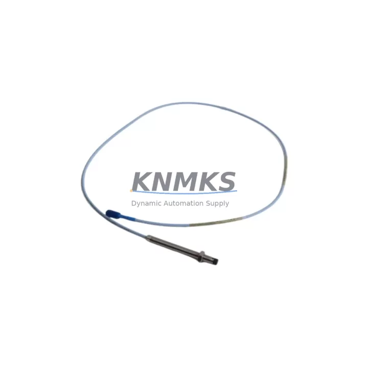
Bently Nevada 330101-32-70-05-12-05 Migration-Ready Proximity Transducer for Legacy Control Systems
The Bently Nevada 330101-32-70-05-12-05 is an 8mm proximity transducer engineered for the 3300 XL series vibration monitoring platform. As legacy rotating machinery protection systems age and OEM support windows close, maintenance engineers face mounting pressure to source tested, drop-in replacements that preserve existing wiring, signal conditioning, and monitor compatibility without triggering a full system overhaul. This unit addresses that challenge directly: it is a migration-ready replacement for discontinued 3300 XL transducer assemblies, supplied tested, with a support terms confirmed by quotation, and available from in-stock inventory for rapid dispatch.
The 330101-32-70-05-12-05 is a complete proximity transducer system comprising the probe, extension cable, and Proximitor® sensor. The part number encodes the key configuration parameters: 8mm probe diameter, 32-inch (approximately 813mm) probe cable, 70-inch (approximately 1778mm) extension cable, standard temperature range, metric thread, and standard gap voltage output. Before substituting this unit into an existing installation, engineers must verify that the existing Proximitor® sensor model — typically a 3300 XL 8mm Proximitor® such as the 330180 series — is compatible with the cable lengths encoded in the replacement SKU. Mismatched cable lengths alter the system scale factor and can introduce measurement error in shaft displacement readings fed to the 3500 series rack monitors or legacy 3300 rack systems.
When integrating this transducer into a 3500 series machinery protection rack, confirm that the target I/O module — such as the 3500/42M Proximitor®/Seismic Monitor or the 3500/40M Proximitor® Monitor — is configured for the correct transducer type and gap voltage range. The 3500 rack’s configuration software (Rack Configuration Software, RCS) must reflect the transducer system scale factor (typically 7.87 V/mm or 200 mV/mil for 8mm probes) to ensure accurate alarm and danger setpoints. If the plant is migrating from an older 3300 rack to a 3500 rack simultaneously, the I/O module slot assignments, channel mapping, and Modbus or RS-232 communication links to the DCS or SCADA historian must all be re-verified before the new rack goes live.
For installations where the existing junction box or field wiring uses the original Bently Nevada armored extension cable with a specific connector type, inspect the mating connector on the 330101-32-70-05-12-05 extension cable before installation. The standard connector is a 9-pin D-sub or equivalent field-wiring termination depending on the plant’s original cable routing standard. If the plant uses a custom junction box with terminal blocks, the extension cable shield grounding point must be maintained at one end only to avoid ground loops that degrade signal integrity on long cable runs in electrically noisy environments such as turbine halls or compressor stations.
Migration Compatibility Table
| Parameter | 330101-32-70-05-12-05 (This Unit) | Legacy / Replaced Unit Notes |
|---|---|---|
| Probe Diameter | 8mm | Must match existing Proximitor® sensor model (330180 series) |
| Probe Cable Length | 32 inches (~813mm) | Verify against existing installation drawing; mismatched length alters scale factor |
| Extension Cable Length | 70 inches (~1778mm) | Total system cable length must match Proximitor® calibration range |
| Thread Standard | Metric (M8) | Confirm bracket/holder thread type before installation |
| Output Signal | Standard gap voltage (–24 VDC bias, 200 mV/mil scale factor) | Compatible with 3500/42M, 3500/40M, and legacy 3300 rack monitors |
| Communication Compatibility | Analog voltage output to monitor I/O module | No protocol change required; DCS/SCADA signal wiring unchanged |
| Installation Space | Standard 8mm probe body; confirm radial clearance in bearing housing | Check probe holder and target material (must be ferromagnetic steel) |
| Firmware / Configuration | No firmware in transducer; RCS configuration update may be required in 3500 rack | Verify scale factor and gap setpoints in RCS before energizing |
| Replacement Recommendation | Direct drop-in for same-SKU or equivalent 3300 XL 8mm transducer systems | Cross-reference OEM part number and cable lengths before ordering |
| Commissioning Focus | Gap voltage verification, scale factor confirmation, alarm setpoint check | Use Bently Nevada gap tool or oscilloscope to verify –12V nominal gap at target |
| Support terms | support terms confirmed by quotation — all units shipped tested and inspected | |
Retrofit Planning for Existing Automation Systems
A successful retrofit of the 330101-32-70-05-12-05 into an operating plant begins well before the maintenance window opens. The first step is a full audit of the existing transducer system: probe condition, extension cable continuity, Proximitor® sensor output voltage, and the gap measurement at the target surface. If the Proximitor® sensor — for example a 330180-51-05 or equivalent 3300 XL 8mm Proximitor® — is also degraded, it should be replaced in the same outage to avoid a repeat shutdown. Replacing only the probe while leaving a marginal Proximitor® in service is a common cause of repeat failures within 6–12 months.
The 3500 series rack housing the monitor channels should be inspected for any I/O module alarms or channel inhibit flags before the outage. If the plant is running a 3500/42M Proximitor®/Seismic Monitor, confirm that the channel assigned to this transducer is not in a latched danger state that could mask a real machinery event during the changeover. The rack’s power supply module — typically a 3500/15 Power Supply — should also be checked for output voltage stability, as a marginal power supply can cause erratic gap readings after a new transducer is installed.
For plants that use a Bently Nevada System 1 software platform or a third-party SCADA historian connected via Modbus TCP or OPC-DA, the channel tag assignments and engineering unit scaling must be confirmed in the historian configuration after the transducer swap. If the plant is simultaneously upgrading from System 1 Evolution to System 1 Orbit, the transducer channel metadata — including probe orientation (X/Y), machine train position, and alarm group membership — must be migrated to the new software database before the outage concludes.
In multi-machine trains where the 330101-32-70-05-12-05 is used on both the driver and driven equipment, it is good practice to replace transducers in matched pairs to maintain consistent signal characteristics across the train. Adjacent channels on the same 3500/42M module that share a common Proximitor® power bus should be checked for cross-channel interference after installation, particularly in high-vibration environments such as gas turbine compressor trains. Signal isolation barriers or Zener barriers used in hazardous area installations must also be verified for compatibility with the replacement transducer’s output impedance.
Downtime Control During System Migration
Minimizing unplanned downtime during a proximity transducer replacement requires a structured pre-outage checklist and a clear rollback plan. Before the maintenance window, the original program logic in the 3500 rack — including channel inhibit sequences, bypass relay assignments, and trip multiply settings — should be exported from the RCS software and saved as a backup configuration file. This ensures that if the new transducer installation reveals an unexpected wiring issue or gap measurement anomaly, the rack can be restored to its previous configuration without re-entering all setpoints manually.
During the physical swap, the probe should be installed in the existing holder with the gap set to the nominal value specified in the machine OEM documentation — typically 1.0mm to 1.5mm for most rotating machinery applications, corresponding to a Proximitor® output of approximately –10V to –12V DC. The gap should be verified with a calibrated gap tool or a precision feeler gauge before the extension cable is reconnected to the Proximitor® sensor. Once the Proximitor® is powered, the output voltage should be measured at the monitor I/O module terminal block to confirm the signal is within the monitor’s input range before the channel inhibit is removed.
For critical machinery where continuous operation is required, a hot-swap procedure using a spare Proximitor® sensor and a temporary signal simulator can maintain the monitor channel in a valid state while the probe is being replaced. This approach is particularly valuable in power generation and petrochemical applications where a single channel trip can initiate a full unit shutdown. After the new transducer is confirmed operational, the channel should be monitored for at least one full operating cycle — including startup transients and steady-state vibration levels — before the maintenance record is closed. All findings, gap measurements, and scale factor verifications should be documented in the plant’s CMMS for future reference and support terms traceability.
Retrofit Support FAQ
Q1: Is the 330101-32-70-05-12-05 a direct replacement for my existing 3300 XL 8mm transducer system?
A: Yes, provided the probe cable length (32 inches), extension cable length (70 inches), thread standard (metric M8), and Proximitor® sensor model are identical to the original installation. Always cross-reference the full part number against your installation drawing before ordering. If your existing system uses a different cable length combination, a different SKU will be required to maintain the correct system scale factor.
Q2: What commissioning steps are required after installation?
A: After physical installation, verify the probe gap voltage at the Proximitor® output (nominal –12V DC at target), confirm the scale factor in the 3500 rack RCS configuration (200 mV/mil for 8mm probes), check all alarm and danger setpoints, remove channel inhibits, and monitor the channel through at least one full operating cycle. Document all measurements in your CMMS for support terms and audit purposes.
Q3: How do I confirm wiring compatibility with my existing junction box?
A: Check the extension cable connector type and pin-out against your junction box terminal block drawing. Verify that the cable shield is grounded at one end only (typically at the Proximitor® sensor end) to prevent ground loops. Confirm that any Zener barriers or signal isolators in the circuit are rated for the Proximitor® output impedance and voltage range.
Q4: What does the support terms confirmed by quotation cover, and how is inventory availability managed?
A: All units are shipped tested and inspected, with a support terms confirmed by quotation covering manufacturing defects and functional performance under normal operating conditions. We maintain in-stock inventory to support urgent maintenance requirements and can provide expedited dispatch for critical plant shutdowns. Contact admin@knmks.com or +86 18359268345 to confirm current stock levels and lead times before raising a purchase order.
© 2026 KNMKS. All rights reserved.
Original Source: https://knmks.com
Contact: admin@knmks.com | +86 18359268345
Product Identification
- Brand / Ecosystem
-
Bently Nevada
Bently Nevada - Model / Series
-
330101-32-70-05-12-05
Bently Nevada 3300 XL / 3301 Series - Product Family
- Sensors
- Availability Status
- Available on request after model and quantity confirmation
- Inquiry Type
- B2B RFQ, replacement inquiry and project spare-part request
- Pre-Quote Check
- Exact SKU, brand, series, quantity, nameplate photos and destination country are checked before quotation
System Path
Where this product fits in the KNMKS automation structure.
Specification & Inquiry Focus
- Sensor range
- Photoelectric, proximity and process sensors
- Common needs
- Output type, distance and connector
- Project support
- Machine detection and replacement inquiry
Buyer Confirmation
Information KNMKS checks before replying.
- Exact model
- 330101-32-70-05-12-05
- Brand / ecosystem
- Bently Nevada
- Product family
- Sensors
- Application note
- Replacement, maintenance, project build or spare-part list
- Useful photos
- Nameplate, installed unit, cabinet layout or connector side
- Delivery details
- Quantity, destination country and target schedule
Document Support
Files and notes can be confirmed during quotation.
- Product photos or nameplate confirmation when available
- Packing and delivery notes before quotation confirmation
- Support scope and delivery terms confirmed per inquiry
- Export document coordination for qualified B2B requests
Inquiry Support
- NPN/PNP, analog and digital output checking
- Connector and cable compatibility review
- Fast inquiry support for maintenance teams
What to Send Us
- Brand and exact model number: Bently Nevada 330101-32-70-05-12-05
- Quantity and required delivery time
- Application, replacement requirement or nameplate photo
- Destination country and shipping preference
RFQ Preparation
This is a product inquiry page built for RFQ communication.
Fast Model Check
Send this model to KNMKS for confirmation.
Include quantity, destination country and photos if this is a maintenance replacement. The inquiry will be saved with a reference number after submission.
Brand & Compatibility Note
KNMKS displays automation product information for well-known industrial brand ecosystems and compatible replacement references. Brand names are used for product identification and compatibility reference only; final availability and commercial terms are confirmed per quotation.
 Manufacturing
 Machine Tools
 Packaging
 Energy & Power



 PLCs & Controllers
 HMI & Displays
 Servo Systems
 Variable Frequency Drives