
Overview
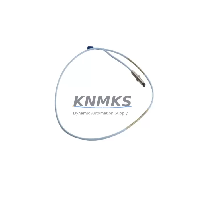
Bently Nevada 330101-00-88-10-02-05 Migration-Ready Proximity Probe for Legacy Control Systems
The Bently Nevada 330101-00-88-10-02-05 is an 8mm eddy-current proximity probe engineered for the 3300 XL Series vibration monitoring platform. As legacy rotating machinery protection systems reach end-of-life and OEM support windows close, this probe remains one of the most requested migration-ready spare parts for facilities operating steam turbines, compressors, pumps, and gearboxes under continuous vibration surveillance. Whether you are executing a planned control system upgrade, responding to an unplanned failure, or building a strategic spare-parts inventory to extend the operational life of your existing 3300 XL infrastructure, the 330101-00-88-10-02-05 provides a verified drop-in replacement path with no firmware modification required at the probe level.
The probe ships pre-calibrated to the standard 200 mV/mil (7.87 V/mm) sensitivity curve used across the 3300 XL family. This calibration is directly compatible with the 3300 XL 8mm Extension Cable (330130 series) and the 3300 XL Proximitor Sensor (330180 series), meaning field technicians can complete a like-for-like swap without reconfiguring the signal conditioning chain. Before installation, engineers should confirm the gap voltage target at the existing Proximitor output — typically –10.0 VDC at the 50-mil (1.27 mm) nominal gap — and verify that the replacement probe’s tip geometry matches the original mounting boss diameter and thread specification (M10 × 1.0 for this variant).
For facilities migrating from older 3300 NSv or 7200 Series probe systems to the current 3300 XL architecture, the 330101-00-88-10-02-05 is frequently deployed alongside the 330130-080-00-00 extension cable and the 330180-X1-05 Proximitor to complete a full channel rebuild. Technicians should audit the existing field wiring for shield continuity and verify that the junction box terminal blocks are rated for the low-level millivolt signals carried on the coaxial interconnect. Any ground loops introduced during the retrofit can produce noise floors that mask real vibration events, so a single-point grounding discipline must be enforced throughout the signal path.
In control cabinet upgrade projects where the rack infrastructure is being modernized from a 3500 Series rack to a newer monitoring architecture, the 330101-00-88-10-02-05 probe can remain in service at the field end while the rack-side I/O modules and communication cards are replaced. This approach minimizes the scope of intrusive work at the machine and reduces the risk of disturbing calibrated probe installations in confined bearing housings. The 3500/42M Proximitor I/O Module and the 3500/22M Transient Data Interface are common rack-side components encountered in these hybrid migration scenarios.
Program compatibility is a critical checkpoint during any probe replacement. The vibration trip setpoints, alert thresholds, and OK relay logic stored in the 3500 rack configuration software must be reviewed against the replacement probe’s sensitivity and scale factor before the system is returned to service. If the plant historian or DCS is receiving 4–20 mA retransmission signals from the monitor rack, the output scaling must be re-verified after the probe swap to ensure the process variable displayed at the operator workstation accurately reflects shaft displacement in engineering units.
HMI screen updates are often overlooked during probe replacements. If the existing SCADA or DCS faceplate displays a channel tag name or engineering unit label tied to the old probe’s serial number or calibration record, those references should be updated in the HMI database to maintain traceability. This is particularly important in facilities subject to API 670 compliance audits, where the as-built documentation must match the installed hardware.
Migration Compatibility Table
| Parameter | 330101-00-88-10-02-05 (This Unit) | Retrofit Notes |
|---|---|---|
| Probe Diameter | 8 mm | Confirm existing mounting boss is M10 × 1.0 thread |
| Sensitivity | 200 mV/mil (7.87 V/mm) | Match to Proximitor scale factor; no recalibration needed for like-for-like swap |
| Cable Length | Probe body only — specify extension cable separately (330130 series) | Measure field run; order correct 330130 extension length |
| Compatible Proximitor | 3300 XL Proximitor (330180 series) | Verify Proximitor firmware version supports 8mm probe type |
| Compatible Rack | 3500 Series Monitor Rack | Check 3500/42M I/O module slot assignment and channel address |
| Communication Protocol | Analog (–24 VDC loop); rack handles Modbus/FOUNDATION Fieldbus output | No protocol change at probe level; verify rack communication card settings |
| Installation Space | Standard 8mm probe boss; 25 mm minimum clearance behind tip | Confirm radial clearance in bearing housing before installation |
| Gap Voltage Target | –10.0 VDC ± 0.5 VDC at 50 mil (1.27 mm) | Set gap with feeler gauge; verify at Proximitor OK output before energizing rack |
| Firmware Compatibility | No probe-level firmware; rack firmware must support 3300 XL probe type | Update 3500 rack firmware if running version older than current release |
| Support terms | support terms confirmed by quotation — covers manufacturing defects; includes pre-shipment functional test report | |
Retrofit Planning for Existing Automation Systems
A successful proximity probe retrofit begins well before the maintenance window opens. The first step is a full channel audit: pull the existing probe’s calibration certificate, record the installed gap voltage, and photograph the terminal block wiring at the junction box. This baseline documentation protects the team if the replacement probe produces an unexpected OK relay state during commissioning.
The 330101-00-88-10-02-05 is most commonly deployed in systems where the 330130-080-00-00 extension cable runs from the machine bearing housing to a field junction box, and from there a 330130-050-00-00 armored interconnect cable continues to the 3500 rack room. When replacing only the probe body, the extension cable connectors must be inspected for corrosion and the coaxial center pin must be clean and undamaged. A contaminated connector is the most frequent cause of a false OK dropout immediately after a probe replacement.
In systems where the 3500/22M Transient Data Interface is installed for startup and coast-down data capture, the probe replacement should be coordinated with the condition monitoring team so that a baseline waveform can be captured immediately after the machine returns to service. This waveform serves as the new reference for future trend analysis and confirms that the replacement probe is tracking shaft motion correctly.
For plants that are simultaneously upgrading their control infrastructure — for example, migrating from a legacy Allen-Bradley PLC-5 or Siemens S5 controller to a ControlLogix or S7-1500 platform — the vibration monitoring system often operates as an independent protection layer. In these cases, the 3500 rack’s Modbus TCP or FOUNDATION Fieldbus output card must be reconfigured to communicate with the new DCS or safety PLC. The probe itself is unaffected by this communication migration, but the rack-level I/O mapping and the DCS tag database must be updated in parallel.
Signal isolators are frequently required when the 3500 rack’s analog retransmission outputs are connected to a new DCS input card with a different common-mode voltage range. A DIN-rail-mounted signal isolator inserted between the rack output and the DCS input card eliminates ground loop interference and protects the sensitive Proximitor circuitry from voltage transients generated by the new control hardware.
Installation space confirmation is non-negotiable. The 8mm probe tip requires a minimum of 25 mm of radial clearance behind the target surface, and the probe body must be secured with the correct anti-rotation locknut torqued to the manufacturer’s specification. In confined bearing housings on older machinery, this clearance is sometimes marginal, and a probe body that is even slightly over-length will contact the shaft — a condition that destroys both the probe and the shaft journal within seconds of startup.
Downtime Control During System Migration
Minimizing unplanned downtime during a proximity probe replacement requires a pre-staged spare kit and a written switching procedure reviewed by the control room operator before the maintenance window begins. The 330101-00-88-10-02-05 ships with a pre-shipment functional test report confirming sensitivity, OK voltage range, and insulation resistance, which allows the maintenance team to verify the replacement unit on the bench before the machine is shut down.
The recommended sequence for a live-system probe replacement is: (1) notify the DCS operator and place the affected channel in bypass mode to prevent a spurious trip during the swap; (2) de-energize the Proximitor by removing the –24 VDC loop supply at the rack terminal block — do not disconnect the probe cable at the machine end while the Proximitor is energized, as the resulting voltage transient can damage the Proximitor input circuit; (3) replace the probe body and re-establish the gap; (4) re-energize the Proximitor and verify the OK relay closes within the expected gap voltage window; (5) remove the channel bypass and confirm the vibration reading is stable and within the historical baseline band before returning the machine to service.
Original program logic stored in the 3500 rack configuration does not need to be modified for a like-for-like probe replacement. Trip setpoints, alert thresholds, and time-delay settings are preserved in the rack’s non-volatile memory and remain active throughout the probe swap. However, if the replacement is part of a broader system upgrade that includes a rack firmware update, the configuration file should be backed up to the 3500 Rack Configuration Software before the firmware is flashed, and the configuration should be reloaded and verified after the update is complete.
Field control continuity is maintained by keeping the machine in operation on the remaining channels while the affected channel is in bypass. For machines with redundant probe installations (X-Y probe pairs), the Y-channel continues to provide protection during the X-channel replacement, provided the rack is configured for OR-gate trip logic on the redundant pair. This approach eliminates the need for a full machine shutdown in most planned maintenance scenarios and reduces the total downtime exposure to the duration of the probe swap itself — typically 30 to 90 minutes for an experienced field technician.
Retrofit Support FAQ
Q: Is the 330101-00-88-10-02-05 a direct replacement for the discontinued 330101-00-88-10-00-05 and similar legacy variants?
A: Yes. The 330101-00-88-10-02-05 is the current production variant and is backward-compatible with the 3300 XL Proximitor and 3500 rack infrastructure used with earlier 330101 series probes. The sensitivity curve, connector type, and thread specification are unchanged. Verify the extension cable part number matches the installed run length before ordering.
Q: What commissioning checks are required after installation?
A: After setting the probe gap to achieve –10.0 VDC ± 0.5 VDC at the Proximitor output, verify that the OK relay is closed, the vibration reading is within the historical baseline band, and the channel is not in alarm or trip state. If the 3500 rack is equipped with a 3500/22M Transient Data Interface, capture a startup waveform for baseline documentation. Remove the channel bypass only after all checks are complete.
Q: Can this probe be used with a 3500/42M Proximitor I/O Module in a rack that also hosts 7200 Series channels?
A: The 3500/42M module supports 3300 XL probe types on its designated channels. Mixed-probe racks are supported provided each channel’s probe type is correctly configured in the 3500 Rack Configuration Software. Do not mix 3300 XL and 7200 Series probes on the same Proximitor I/O module channel without verifying the module’s firmware supports the mixed configuration.
Q: What does the support terms confirmed by quotation cover, and is a test report included?
A: The support terms confirmed by quotation cover manufacturing defects in materials and workmanship from the date of shipment. Each unit ships with a pre-shipment functional test report documenting sensitivity, OK voltage range, and insulation resistance. In-stock units are available for same-week dispatch. Contact admin@knmks.com or +86 18359268345 for lead time confirmation and volume pricing.
© 2026 KNMKS. All rights reserved.
Original Source: https://knmks.com
Contact: admin@knmks.com | +86 18359268345
Product Identification
- Brand / Ecosystem
-
Bently Nevada
Bently Nevada - Model / Series
-
330101-00-88-10-02-05
Bently Nevada 3300 XL / 3301 Series - Product Family
- Sensors
- Availability Status
- Available on request after model and quantity confirmation
- Inquiry Type
- B2B RFQ, replacement inquiry and project spare-part request
- Pre-Quote Check
- Exact SKU, brand, series, quantity, nameplate photos and destination country are checked before quotation
System Path
Where this product fits in the KNMKS automation structure.
Specification & Inquiry Focus
- Sensor range
- Photoelectric, proximity and process sensors
- Common needs
- Output type, distance and connector
- Project support
- Machine detection and replacement inquiry
Buyer Confirmation
Information KNMKS checks before replying.
- Exact model
- 330101-00-88-10-02-05
- Brand / ecosystem
- Bently Nevada
- Product family
- Sensors
- Application note
- Replacement, maintenance, project build or spare-part list
- Useful photos
- Nameplate, installed unit, cabinet layout or connector side
- Delivery details
- Quantity, destination country and target schedule
Document Support
Files and notes can be confirmed during quotation.
- Product photos or nameplate confirmation when available
- Packing and delivery notes before quotation confirmation
- Support scope and delivery terms confirmed per inquiry
- Export document coordination for qualified B2B requests
Inquiry Support
- NPN/PNP, analog and digital output checking
- Connector and cable compatibility review
- Fast inquiry support for maintenance teams
What to Send Us
- Brand and exact model number: Bently Nevada 330101-00-88-10-02-05
- Quantity and required delivery time
- Application, replacement requirement or nameplate photo
- Destination country and shipping preference
RFQ Preparation
This is a product inquiry page built for RFQ communication.
Fast Model Check
Send this model to KNMKS for confirmation.
Include quantity, destination country and photos if this is a maintenance replacement. The inquiry will be saved with a reference number after submission.
Brand & Compatibility Note
KNMKS displays automation product information for well-known industrial brand ecosystems and compatible replacement references. Brand names are used for product identification and compatibility reference only; final availability and commercial terms are confirmed per quotation.
 Manufacturing
 Machine Tools
 Packaging
 Energy & Power



 PLCs & Controllers
 HMI & Displays
 Servo Systems
 Variable Frequency Drives