
Overview
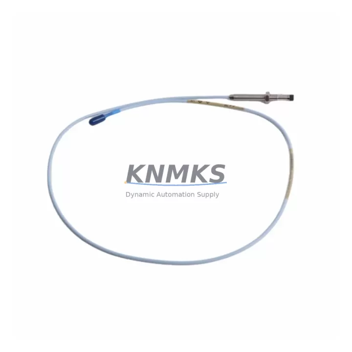
Bently Nevada 330101-00-77-15-12-05 Migration-Ready Proximity Transducer for Legacy Control Systems
The Bently Nevada 330101-00-77-15-12-05 is an 8mm proximity transducer engineered for the 3300 XL Series continuous machinery monitoring platform. As legacy Bently Nevada 3300 Series installations approach end-of-support milestones, this module serves as a verified migration-ready replacement for facilities undertaking control system modernization, spare parts lifecycle extension, and predictive maintenance infrastructure upgrades. Whether you are replacing a discontinued transducer in a running train, retrofitting a vibration monitoring loop in a compressor control cabinet, or rebuilding a complete 3300 XL rack after a field failure, the 330101-00-77-15-12-05 provides the dimensional, electrical, and signal compatibility required for a low-risk, minimum-downtime swap.
Before committing to a replacement order, engineers should confirm the following parameters against the existing installation: driver/extension cable pairing (the 330101-00-77-15-12-05 is designed for use with the 330130 extension cable and 330180 driver), gap voltage at the operating air gap (typically –10 VDC at 1.0 mm for 3300 XL-calibrated systems), power supply rail from the monitor chassis (–24 VDC nominal), terminal block wiring polarity at the 3300 XL monitor input card, and the physical probe tip-to-target clearance within the bearing housing. Confirming these six parameters before removal of the legacy transducer eliminates the majority of commissioning delays encountered during field retrofits.
Migration Compatibility Table
| Parameter | 330101-00-77-15-12-05 Specification | Legacy 3300 Series Requirement | Retrofit Note |
|---|---|---|---|
| Probe Diameter | 8 mm | 8 mm | Direct drop-in; no housing modification required |
| Cable Length | 5m (integral) | 5m standard | Verify total system length with 330130 extension |
| Supply Voltage | –24 VDC | –24 VDC | Confirm monitor card power rail before installation |
| Output Sensitivity | 200 mV/mil (7.87 V/mm) | 200 mV/mil | No scale factor change in 3300 XL monitor configuration |
| Linear Range | 0.25 – 2.25 mm | 0.25 – 2.25 mm | Re-verify gap after installation; target –10 VDC at 1.0 mm |
| Connector / Termination | Integral coaxial, MIL-C-17 compatible | Coaxial | Inspect extension cable connector for wear before reuse |
| Monitor Compatibility | 3300 XL 11 mm, 3300 XL 8 mm monitors | 3300 XL rack-mounted monitors | Confirm monitor firmware revision supports 8 mm calibration |
| Installation Space | Standard 8 mm probe boss | Standard 8 mm probe boss | No machining required for standard installations |
| Communication Protocol | Analog (4–20 mA / voltage output via monitor) | Analog | DCS/PLC signal wiring unchanged; verify monitor output card |
| Support terms | support terms confirmed by quotation from date of shipment. Covers manufacturing defects under normal operating conditions. | ||
Retrofit Planning for Existing Automation Systems
A successful 3300 XL transducer retrofit begins well before the maintenance window opens. The first step is a rack-level audit of the existing Bently Nevada 3300 XL monitor chassis: identify which monitor cards — such as the 3300/20 Radial Vibration Monitor or the 3300/25 Thrust Position Monitor — are currently paired with the transducer being replaced, and pull the current configuration printout from the System 1 software or the local keypad display. This configuration data governs the alert and danger setpoints, the full-scale range, and the OK relay logic that downstream DCS or safety systems depend on.
Next, inspect the 330130 extension cable that connects the 330101-00-77-15-12-05 probe to the monitor input. Extension cables are frequently overlooked during transducer replacements, yet a damaged or corroded coaxial connector is one of the most common causes of post-retrofit signal noise and false OK-relay trips. If the extension cable shows any jacket cracking, connector corrosion, or impedance deviation from the 50-ohm nominal, replace it alongside the probe. Similarly, the 330180 driver (proximitor) should be inspected for moisture ingress and output voltage stability before the new transducer is gapped.
For facilities running Bently Nevada System 1 Evolution software, the transducer replacement does not require a software license change, but the channel configuration should be reviewed to confirm that the transducer type, sensitivity, and gap voltage parameters match the 330101-00-77-15-12-05 calibration curve. If the existing installation used an older 7200 Series transducer as an interim replacement, the sensitivity factor in System 1 must be updated from 100 mV/mil to 200 mV/mil to avoid a 2× scaling error on all vibration readings.
Where the control cabinet includes a 3500 Series rack alongside the 3300 XL equipment — a common configuration in turbine control upgrades — verify that the 3500/42M Proximitor I/O Module or the 3500/40M Proximitor Monitor is not sharing a common power supply rail with the 3300 XL chassis. Cross-rail power contamination can introduce ground loops that manifest as low-frequency noise on the vibration channel after the new transducer is installed. A dedicated –24 VDC supply for the 3300 XL rack eliminates this risk. If the cabinet also houses a Bently Nevada 3500/22M Transient Data Interface for startup and coast-down capture, confirm that the new transducer’s channel assignment is correctly mapped in the TDI configuration before the next machine run.
Finally, if the retrofit is part of a broader migration from the 3300 XL platform to the 3500 Series or to a third-party vibration monitoring system, document the existing wiring terminations at the monitor card terminal block before disconnecting anything. Photograph the terminal strip, record the wire colors and signal assignments, and verify that the replacement monitor’s input impedance is compatible with the 330101-00-77-15-12-05 output characteristics. This documentation step costs less than 15 minutes and eliminates the most common source of post-migration commissioning delays.
Downtime Control During System Migration
Minimizing unplanned downtime during a transducer replacement on a running production line requires a structured pre-work sequence. Begin by placing the affected monitor channel into bypass mode within the 3300 XL monitor or the System 1 software — this prevents a spurious danger trip from the DCS or ESD system while the transducer is disconnected. Confirm with the control room that the bypass is active and that the machine protection logic has been temporarily transferred to redundant channels or alternative protection devices before breaking any connections.
With the channel bypassed, remove the existing transducer and extension cable assembly as a unit. Do not disconnect the extension cable from the proximitor in the field unless the cable itself is being replaced — unnecessary connector cycling degrades the coaxial interface and can introduce impedance mismatches that are difficult to diagnose after reassembly. Install the 330101-00-77-15-12-05 and its associated extension cable, then set the air gap to the target value using a calibrated gap-setting tool and a digital voltmeter on the proximitor output. The target gap voltage for a 3300 XL-calibrated 8 mm system is –10.0 VDC ±0.5 VDC at a 1.0 mm air gap.
Once the gap is set and the output voltage is confirmed stable, remove the channel bypass in the monitor and observe the vibration reading for a minimum of five minutes before returning the machine to normal protection status. Compare the new baseline vibration amplitude and phase against the historical trend data in System 1 to confirm that the replacement transducer is tracking correctly. Any amplitude deviation greater than 10% from the pre-replacement baseline warrants a gap recheck and a cable continuity verification before the bypass is permanently removed. This structured commissioning sequence — bypass, replace, gap, verify, restore — consistently achieves transducer replacements in under two hours without interrupting production on adjacent machinery trains.
Retrofit Support FAQ
Q: Is the 330101-00-77-15-12-05 a direct replacement for the discontinued 330101-00-77-10-02-05?
A: The 330101-00-77-15-12-05 and the 330101-00-77-10-02-05 share the same 8 mm probe diameter, –24 VDC supply requirement, and 200 mV/mil sensitivity, making the former a functionally compatible replacement in the majority of 3300 XL installations. The primary difference is cable length (15m vs. 10m integral cable). If the existing installation uses a 10m cable run, the additional 5m of integral cable on the 330101-00-77-15-12-05 must be coiled and secured inside the junction box or conduit run. Verify that the total system cable length — probe integral cable plus 330130 extension — does not exceed the maximum specified for the paired 330180 driver.
Q: What pre-shipment testing is performed on each unit?
A: Each 330101-00-77-15-12-05 unit undergoes output voltage linearity verification across the full 0.25–2.25 mm linear range, coaxial cable continuity and impedance check, and connector integrity inspection prior to shipment. A test report is available upon request. Units are shipped in anti-static packaging with a calibration sticker indicating the test date and technician ID.
Q: What is the support terms coverage and what does it include?
A: All units carry a support terms confirmed by quotation from the date of shipment. The support terms covers manufacturing defects in materials and workmanship under normal operating conditions as specified in the Bently Nevada 330101 Series product manual. It does not cover damage resulting from incorrect gap setting, supply voltage outside the –24 VDC ±10% tolerance, or installation in environments exceeding the rated temperature range. Support requests are processed within 5 business days of receipt of the returned unit.
Q: Can this transducer be used with non-Bently Nevada monitor systems?
A: The 330101-00-77-15-12-05 produces a standard analog voltage output via the paired proximitor driver, making it electrically compatible with any monitor or PLC analog input card that accepts a –24 VDC-powered eddy-current transducer signal in the –2 VDC to –18 VDC output range. However, the calibration curve and sensitivity factor (200 mV/mil) must be correctly entered in the third-party monitor’s configuration. Compatibility with non-Bently Nevada systems should be verified by the end user’s instrumentation engineer before installation. Contact admin@knmks.com for application-specific compatibility guidance.
© 2026 KNMKS. All rights reserved.
Original Source: https://knmks.com
Contact: admin@knmks.com | +86 18359268345
Product Identification
- Brand / Ecosystem
-
Bently Nevada
Bently Nevada - Model / Series
-
330101-00-77-15-12-05
Bently Nevada 3300 XL / 3301 Series - Product Family
- Sensors
- Availability Status
- Available on request after model and quantity confirmation
- Inquiry Type
- B2B RFQ, replacement inquiry and project spare-part request
- Pre-Quote Check
- Exact SKU, brand, series, quantity, nameplate photos and destination country are checked before quotation
System Path
Where this product fits in the KNMKS automation structure.
Specification & Inquiry Focus
- Sensor range
- Photoelectric, proximity and process sensors
- Common needs
- Output type, distance and connector
- Project support
- Machine detection and replacement inquiry
Buyer Confirmation
Information KNMKS checks before replying.
- Exact model
- 330101-00-77-15-12-05
- Brand / ecosystem
- Bently Nevada
- Product family
- Sensors
- Application note
- Replacement, maintenance, project build or spare-part list
- Useful photos
- Nameplate, installed unit, cabinet layout or connector side
- Delivery details
- Quantity, destination country and target schedule
Document Support
Files and notes can be confirmed during quotation.
- Product photos or nameplate confirmation when available
- Packing and delivery notes before quotation confirmation
- Support scope and delivery terms confirmed per inquiry
- Export document coordination for qualified B2B requests
Inquiry Support
- NPN/PNP, analog and digital output checking
- Connector and cable compatibility review
- Fast inquiry support for maintenance teams
What to Send Us
- Brand and exact model number: Bently Nevada 330101-00-77-15-12-05
- Quantity and required delivery time
- Application, replacement requirement or nameplate photo
- Destination country and shipping preference
RFQ Preparation
This is a product inquiry page built for RFQ communication.
Fast Model Check
Send this model to KNMKS for confirmation.
Include quantity, destination country and photos if this is a maintenance replacement. The inquiry will be saved with a reference number after submission.
Brand & Compatibility Note
KNMKS displays automation product information for well-known industrial brand ecosystems and compatible replacement references. Brand names are used for product identification and compatibility reference only; final availability and commercial terms are confirmed per quotation.
 Manufacturing
 Machine Tools
 Packaging
 Energy & Power



 PLCs & Controllers
 HMI & Displays
 Servo Systems
 Variable Frequency Drives