
Overview
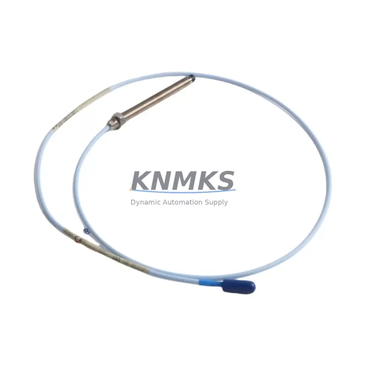
Bently Nevada 330101-00-48-10-02-00 3300 XL Retrofit Probe: Migration-Ready Replacement for Legacy Vibration Monitoring Systems
The Bently Nevada 330101-00-48-10-02-00 is a 3300 XL Series proximity probe engineered for direct retrofit into legacy vibration monitoring and machinery protection systems. As industrial facilities accelerate the decommissioning of aging 3300 Series platforms, this probe provides a validated, migration-ready replacement path that preserves existing wiring infrastructure, Proximitor signal conditioning, and DCS integration — minimizing engineering rework and unplanned downtime during system changeover.
Designed for radial and axial shaft displacement measurement on rotating machinery including turbines, compressors, pumps, and gearboxes, the 330101-00-48-10-02-00 delivers the 5 mm/V sensitivity standard required by the 3300 XL platform. Its 48-inch (1219 mm) probe cable length and 10-32 UNF thread mounting are dimensionally compatible with the majority of legacy probe installations, allowing direct swap without bracket modification or re-drilling.
When planning a retrofit from an earlier 3300 Series or TK-3 proximity system, engineers must verify several critical parameters before commissioning. Power supply capacity at the Proximitor — typically the 3300/16 or 3300/20 — must be confirmed to support the probe’s operating range of −18 VDC to −24 VDC. Terminal block wiring at the junction box should be inspected for correct shield grounding and conductor continuity, particularly where cable runs exceed 5 meters and signal attenuation risk increases. Backplane slot assignments in the 3500 Series rack (if migrating upward) must be re-mapped to match the new channel configuration, and module addresses updated in the System 1 software database accordingly.
Program logic compatibility is a frequent concern during 3300-to-3500 migrations. Existing alarm setpoints, gap voltage calibration values, and OK relay logic stored in the 3300/20 monitor must be documented and re-entered into the replacement 3500/42M or 3500/40M monitor module. HMI screens built on GE Cimplicity, Wonderware InTouch, or Yokogawa FAST/TOOLS that reference the old tag structure will require tag remapping to reflect the new rack and slot addressing. Communication links using Modbus RTU or Ethernet/IP to the plant DCS should be re-tested after migration to confirm data integrity and alarm propagation.
Installation space confirmation is essential in congested control cabinets. The 330101-00-48-10-02-00 probe body diameter and extension cable routing must be verified against available clearance at the bearing housing. Where space is constrained, the companion 330130-080-00-00 extension cable or 330180-X0-05 armored cable assembly may be substituted to achieve the required total system length without compromising signal quality. The 3300 XL Proximitor 3300/55 or 3300/65 should be confirmed as firmware-compatible with the probe model prior to installation.
Firmware version alignment between the Proximitor and the monitoring rack is a commonly overlooked step that can cause false OK relay trips during initial commissioning. Always cross-reference the Proximitor firmware revision against the 3500 rack firmware matrix before energizing the system. Field calibration using a Bently Nevada calibration standard or equivalent gap simulator should be performed at the probe tip to verify the −18 VDC gap voltage at the nominal 1.0 mm gap, confirming the probe is operating within the linear range of the 3300 XL system.
Migration Compatibility Table
| Parameter | 330101-00-48-10-02-00 (3300 XL) | Legacy 3300 Series Reference |
|---|---|---|
| Probe Thread | 10-32 UNF | 10-32 UNF (compatible) |
| Cable Length | 48 in (1219 mm) | Verify total system length with extension |
| Sensitivity | 5 mm/V (200 mV/mil) | 5 mm/V (direct replacement) |
| Supply Voltage | −18 VDC to −24 VDC | Confirm Proximitor output capacity |
| Compatible Proximitor | 3300/55, 3300/65 | 3300/16, 3300/20 (verify firmware) |
| Target Material | AISI 4140 steel (standard) | Confirm shaft material for calibration |
| Communication | Analog (4–20 mA via monitor) | Modbus RTU / Ethernet/IP via 3500 rack |
| Installation | Direct bracket swap in most applications | Verify clearance at bearing housing |
| Commissioning | Gap calibration at −18 VDC nominal | Re-enter setpoints from legacy monitor |
| Support terms | support terms confirmed by quotation — tested before shipment | |
Retrofit Planning for Existing Automation Systems
A successful retrofit of the 330101-00-48-10-02-00 into an operating plant environment requires coordinated planning across multiple system layers. The probe itself is the field-level sensing element, but its performance depends on the integrity of the complete measurement chain: extension cable, Proximitor, monitor module, rack backplane, and software configuration.
Begin by auditing the existing 3300/20 monitor module for alarm setpoint documentation. These values — including direct vibration danger and alert levels, gap voltage OK limits, and relay output assignments — must be preserved and re-entered into the replacement 3500/42M monitor. The 3500 rack’s backplane accepts the 3500/42M in a standard two-slot configuration; confirm that adjacent slots are not occupied by incompatible modules such as the 3500/61 or 3500/64 communication gateway, which may require re-addressing after the probe channel is added.
For I/O expansion during the same maintenance window, the 3500/20 rack interface module can be used to add additional proximity channels without requiring a separate rack. If the facility is also upgrading temperature or process variable monitoring, the 3500/60 Ethernet communications module provides a unified Modbus TCP gateway for all rack channels, simplifying DCS integration and reducing the number of serial communication links to maintain.
Where the existing control cabinet includes a Bently Nevada 3300/55 Proximitor mounted on a DIN rail, the 330101-00-48-10-02-00 probe connects directly using the standard coaxial connector. If the cabinet layout requires routing the extension cable through conduit shared with power wiring, specify the 330180-X0-05 armored extension cable to prevent electromagnetic interference from affecting the probe signal. Signal isolation barriers may be required at the DCS analog input card if the facility’s grounding scheme does not meet ISA-S82.01 requirements.
Programming cable access for the 3500 rack is typically provided via the 3500/92 or 3500/93 communication interface. Ensure the System 1 software version installed on the engineering workstation is compatible with the rack firmware before attempting to download the updated configuration. A pre-migration backup of the existing rack configuration file should be stored on a separate drive as a rollback reference.
Downtime Control During System Migration
Minimizing production interruption during a proximity probe retrofit requires a structured pre-outage preparation protocol. All replacement components — including the 330101-00-48-10-02-00 probe, extension cable, and any required Proximitor — should be bench-tested and gap-calibrated before the maintenance window begins. This allows the field team to confirm probe linearity and Proximitor output voltage before the machine is taken offline, reducing the risk of discovering a defective component during a time-critical outage.
The original program logic from the 3300/20 monitor should be exported and reviewed against the new 3500/42M configuration template at least 48 hours before the planned outage. Any discrepancies in channel numbering, alarm logic, or relay output assignments should be resolved in the engineering environment before the rack is powered down. This step is particularly important where the proximity channels feed into a turbine protection system or compressor surge control loop, where incorrect alarm setpoints could trigger spurious trips during restart.
During the physical swap, maintain continuity of the machine’s lube oil system and seal gas supply where applicable, as these systems may have independent monitoring that remains active during the electrical outage. After the new probe is installed and the Proximitor is energized, verify the gap voltage reading at the monitor before closing the junction box. Confirm that the OK relay is energized and that the vibration reading is within the expected baseline range for the machine at rest before releasing the unit for restart.
Post-restart trending in System 1 or the plant historian should be monitored for the first 24 hours of operation to confirm that the new probe is tracking correctly and that no alarm nuisance trips occur. Document the as-found and as-left gap voltage readings, probe serial number, and installation date in the plant maintenance management system for future reference and support terms tracking.
Retrofit Support FAQ
Q: Is the 330101-00-48-10-02-00 a direct replacement for the earlier 330101-00-48-10-00-00?
A: Yes. The 330101-00-48-10-02-00 is the current production revision of the 330101-00-48-10-00-00 and is dimensionally and electrically compatible. The probe thread, cable length, sensitivity, and Proximitor interface are unchanged. No wiring or bracket modification is required for a direct swap.
Q: What commissioning steps are required after installation?
A: After physical installation, set the probe gap to the nominal value specified for the machine (typically 1.0–1.5 mm for most rotating equipment). Verify the Proximitor output voltage is within the −18 VDC to −24 VDC OK range. Re-enter alarm setpoints in the 3500/42M monitor, confirm relay output logic, and perform a functional test of the OK relay before releasing the machine for operation.
Q: Can this probe be used with a 3500 Series rack without a 3300 XL Proximitor?
A: The 330101-00-48-10-02-00 requires a 3300 XL Proximitor (such as the 3300/55 or 3300/65) as the signal conditioning element. It is not designed for direct connection to a 3500 Series monitor without the Proximitor in the signal chain. The Proximitor converts the probe’s eddy-current signal to a voltage output compatible with the 3500/42M monitor input.
Q: What support terms and pre-shipment testing does KNMKS provide?
A: Every 330101-00-48-10-02-00 unit shipped by KNMKS is tested for electrical continuity, gap voltage linearity, and connector integrity before dispatch. A support terms confirmed by quotation is provided from the date of shipment, covering manufacturing defects and premature failure under normal operating conditions. Expedited shipping and in-stock availability are confirmed at time of order.
© 2026 KNMKS. All rights reserved.
Original Source: https://knmks.com
Contact: admin@knmks.com | +86 18359268345
Product Identification
- Brand / Ecosystem
-
Bently Nevada
Bently Nevada - Model / Series
-
330101-00-48-10-02-00
Bently Nevada 3300 XL / 3301 Series - Product Family
- Sensors
- Availability Status
- Available on request after model and quantity confirmation
- Inquiry Type
- B2B RFQ, replacement inquiry and project spare-part request
- Pre-Quote Check
- Exact SKU, brand, series, quantity, nameplate photos and destination country are checked before quotation
System Path
Where this product fits in the KNMKS automation structure.
Specification & Inquiry Focus
- Sensor range
- Photoelectric, proximity and process sensors
- Common needs
- Output type, distance and connector
- Project support
- Machine detection and replacement inquiry
Buyer Confirmation
Information KNMKS checks before replying.
- Exact model
- 330101-00-48-10-02-00
- Brand / ecosystem
- Bently Nevada
- Product family
- Sensors
- Application note
- Replacement, maintenance, project build or spare-part list
- Useful photos
- Nameplate, installed unit, cabinet layout or connector side
- Delivery details
- Quantity, destination country and target schedule
Document Support
Files and notes can be confirmed during quotation.
- Product photos or nameplate confirmation when available
- Packing and delivery notes before quotation confirmation
- Support scope and delivery terms confirmed per inquiry
- Export document coordination for qualified B2B requests
Inquiry Support
- NPN/PNP, analog and digital output checking
- Connector and cable compatibility review
- Fast inquiry support for maintenance teams
What to Send Us
- Brand and exact model number: Bently Nevada 330101-00-48-10-02-00
- Quantity and required delivery time
- Application, replacement requirement or nameplate photo
- Destination country and shipping preference
RFQ Preparation
This is a product inquiry page built for RFQ communication.
Fast Model Check
Send this model to KNMKS for confirmation.
Include quantity, destination country and photos if this is a maintenance replacement. The inquiry will be saved with a reference number after submission.
Brand & Compatibility Note
KNMKS displays automation product information for well-known industrial brand ecosystems and compatible replacement references. Brand names are used for product identification and compatibility reference only; final availability and commercial terms are confirmed per quotation.
 Manufacturing
 Machine Tools
 Packaging
 Energy & Power



 PLCs & Controllers
 HMI & Displays
 Servo Systems
 Variable Frequency Drives