
Overview
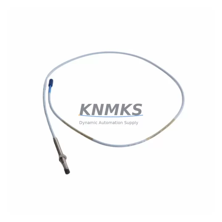
Bently Nevada 330101-00-45-20-12-05 Migration-Ready Proximity Transducer for Legacy Control Systems
The Bently Nevada 330101-00-45-20-12-05 is an 8mm proximity transducer engineered for seamless integration into legacy vibration monitoring and machinery protection systems. As industrial facilities accelerate the retirement of aging control infrastructure, this transducer serves as a verified drop-in replacement for discontinued 3300 XL series components, enabling engineers to restore full system functionality without redesigning the measurement chain or rewriting existing monitoring logic.
When planning a retrofit around the 330101-00-45-20-12-05, engineers must confirm several critical parameters before committing to installation. Power supply compatibility is the first checkpoint: the transducer requires a regulated –24 VDC supply, and the existing driver or proximitor module — typically a Bently Nevada 3300 XL 8mm Proximitor such as the 330180-X1-05 — must be verified to deliver the correct bias voltage within the –10 VDC to –18 VDC output range. If the original proximitor has been removed or is no longer serviceable, a replacement proximitor module must be sourced and bench-tested alongside the transducer before field installation.
Terminal wiring is the next area of focus. The 330101-00-45-20-12-05 uses a standard coaxial cable assembly terminated with an Armored Extension Cable, and the field wiring must be inspected for continuity, shield integrity, and correct polarity at the junction box. Any substitution of cable type or length will shift the system scale factor and must be recalibrated against the proximitor’s output curve. Engineers retrofitting older 3300 series racks should also verify that the I/O terminal block assignments in the existing rack — including the Bently Nevada 3300/16 I/O Module or equivalent — match the new wiring diagram before energizing the loop.
Backplane and rack interface compatibility must be confirmed when the transducer is being reinstated into a 3300 XL rack alongside other active modules. The rack’s power budget should be recalculated if additional I/O cards, communication modules, or relay output modules have been added since the original installation. Module address settings and DIP switch configurations on adjacent cards must remain unchanged to avoid conflicts with the System 1 or System 1 Evolution software that reads the measurement data.
Program and HMI compatibility is equally important. Facilities running Bently Nevada System 1 software must confirm that the transducer’s gap voltage, scale factor, and measurement range are correctly entered in the channel configuration. HMI screens displaying shaft vibration, gap, and 1X/2X vectors should be reviewed after replacement to ensure that alarm setpoints and trend baselines remain valid. If the control system communicates vibration data upstream to a DCS or SCADA platform via Modbus RTU or Ethernet/IP, the communication link should be tested end-to-end after the transducer swap to confirm that data integrity is maintained.
Installation space must be verified at the machine bearing housing. The 330101-00-45-20-12-05 has a defined probe body length and thread specification (M10 × 1 thread, 45 mm probe length) that must match the existing mounting boss dimensions. If the original probe was a different length variant — such as the 330101-00-60-10-02 or 330101-00-30-10-02 — the gap setting procedure must be repeated from scratch using a calibrated gap tool to achieve the correct –10 VDC to –12 VDC nominal gap voltage.
Firmware version compatibility applies to the rack monitor cards. Bently Nevada 3500 series monitor cards used in parallel measurement chains — such as the 3500/42M Proximitor/Seismic Monitor — may require firmware updates if the facility is migrating from an older 3300 XL rack to a 3500 platform as part of a broader system modernization. In mixed-platform environments, the 330101-00-45-20-12-05 transducer is compatible with both platforms, provided the proximitor module is matched correctly.
Migration Compatibility Table
| Parameter | 330101-00-45-20-12-05 Specification | Retrofit / Migration Note |
|---|---|---|
| Probe Thread | M10 × 1, 45 mm body length | Verify mounting boss thread and depth before installation |
| Supply Voltage | –24 VDC (regulated) | Confirm proximitor power rail; replace fuse if blown |
| Output Bias Voltage | –10 VDC to –18 VDC | Recalibrate gap after installation; target –12 VDC nominal |
| Scale Factor | 200 mV/mil (7.87 V/mm) | Update System 1 channel config if scale factor differs from prior probe |
| Cable / Connector | Coaxial, Armored Extension Cable | Inspect shield continuity; replace cable if corroded or kinked |
| Compatible Proximitor | 3300 XL 8mm Proximitor (330180 series) | Match proximitor model to probe length; bench-test before field install |
| Platform Compatibility | 3300 XL, 3500 series racks | Confirm firmware version on 3500/42M if migrating platforms |
| Communication Protocol | Analog (4–20 mA / voltage output via monitor card) | Verify Modbus RTU or Ethernet/IP mapping in DCS after swap |
| Installation Space | Standard bearing housing boss (M10) | Confirm clearance for probe body and cable routing |
| Support terms | support terms confirmed by quotation | Covered from date of shipment; includes functional verification |
Retrofit Planning for Existing Automation Systems
A successful retrofit centered on the 330101-00-45-20-12-05 typically involves more than a single component swap. In most legacy machinery protection panels, the transducer works in concert with a matched proximitor module, a rack-mounted monitor card, and a dedicated power supply module. When the original 3300 XL rack is being decommissioned in favor of a 3500 series platform, engineers must plan the migration of each measurement channel individually.
The 3300 XL 8mm Proximitor (330180-X1-05) is the primary companion module for this transducer. If the proximitor is also discontinued or damaged, it must be replaced simultaneously to ensure the gap voltage and scale factor remain within specification. In 3500 series migrations, the 3500/42M Proximitor/Seismic Monitor card takes over the signal conditioning role, and the transducer’s coaxial cable must be rerouted to the new card’s input terminals.
Power distribution within the control cabinet must be reassessed. The 3300 XL power supply module — often a dedicated –24 VDC rail card — may not be present in a 3500 rack, which uses its own internal power architecture. A standalone –24 VDC power supply or a Bently Nevada 3500/15 Power Supply module must be confirmed as the source for the transducer loop. Signal isolation may also be required if the measurement loop shares a common ground with other instrumentation; in such cases, a DIN-rail-mounted signal isolator should be inserted between the proximitor output and the DCS analog input card.
For facilities that retain the 3300 XL rack but replace only the transducer, the I/O terminal block wiring inside the rack must be inspected and re-torqued. Loose terminals are a common cause of intermittent gap voltage readings that can trigger false alarms in System 1. The programming cable used to access the rack’s configuration — typically a Bently Nevada RS-232 or USB programming cable — should be on hand during commissioning to allow real-time channel verification without interrupting adjacent measurement channels.
HMI screens in System 1 or System 1 Evolution should be reviewed before the machine is returned to service. Trend data from the replaced transducer will show a discontinuity at the point of replacement, and baseline vibration levels should be re-established after a short run-in period. Alarm setpoints for radial vibration, gap, and 1X amplitude should be confirmed against the machine’s original acceptance test data.
Downtime Control During System Migration
Minimizing unplanned downtime during a transducer replacement requires a structured pre-outage checklist. Before the machine is taken offline, the replacement 330101-00-45-20-12-05 should be bench-tested with the matched proximitor to confirm the gap voltage curve and scale factor. All replacement components — including the armored extension cable, terminal ferrules, and any required mounting adapters — should be staged at the work site before the outage window begins.
The original program logic in the DCS or PLC that processes the vibration signal should be documented and backed up before any wiring changes are made. If the monitor card’s channel configuration is stored in non-volatile memory, a configuration export should be saved to a laptop running System 1 software. This ensures that if the card is inadvertently reset during the swap, the channel parameters can be restored in minutes rather than hours.
During the physical swap, the machine’s control system should remain in a safe, de-energized state with appropriate lockout/tagout procedures applied. The new transducer should be installed, gapped, and the coaxial cable connected before power is restored to the measurement loop. After energizing, the gap voltage should be read at the proximitor output and compared against the target value before the monitor card’s OK relay is re-enabled. This sequence protects the original alarm logic from triggering spurious trips during the commissioning phase.
Once the transducer is confirmed in-service, a short supervised run at reduced load allows the engineer to verify that vibration readings are stable and consistent with historical baseline data. Any deviation greater than 10% from the pre-outage baseline should be investigated before the machine is returned to full production load. This approach keeps the total outage window predictable and reduces the risk of a second unplanned shutdown caused by an incomplete retrofit.
Retrofit Support FAQ
Q: Is the 330101-00-45-20-12-05 a direct replacement for other 330101 series variants?
A: The 330101 series shares the same 8mm probe diameter and M10 thread, but probe body length and cable length vary by part number suffix. The -00-45-20-12-05 designates a 45 mm probe body with a 5-meter armored extension cable. Before substituting a different suffix variant, confirm that the probe length matches the bearing housing boss depth and that the total cable length (probe + extension) falls within the proximitor’s specified range. Mixing incompatible lengths will shift the scale factor and require recalibration.
Q: What commissioning steps are required after installation?
A: After physical installation, connect the coaxial cable to the matched proximitor and apply –24 VDC supply power. Measure the DC output voltage at the proximitor’s output terminals and adjust the probe gap until the reading falls within –10 VDC to –12 VDC (nominal –12 VDC for most applications). Confirm the OK relay has closed, then open System 1 or the rack’s configuration software to verify that the channel is reading correctly and that no fault flags are active. Record the as-found gap voltage in the maintenance log before returning the machine to service.
Q: How is outgoing product quality verified before shipment?
A: Each 330101-00-45-20-12-05 unit undergoes functional verification prior to shipment, including continuity testing of the coaxial cable assembly, inspection of the probe tip and thread condition, and confirmation of the probe body dimensions against the manufacturer’s specification. Units are shipped with protective end caps and anti-static packaging. A support terms confirmed by quotation cover manufacturing defects and functional failures from the date of shipment.
Q: What is the typical lead time and inventory availability?
A: Stock availability is maintained for immediate dispatch. Standard orders are processed within 1–2 business days, with express shipping options available for urgent maintenance requirements. For large-quantity orders or long-term supply agreements covering multiple replacement cycles, contact the sales team to discuss reserved inventory arrangements and volume pricing.
© 2026 KNMKS. All rights reserved.
Original Source: https://knmks.com
Contact: admin@knmks.com | +86 18359268345
Product Identification
- Brand / Ecosystem
-
Bently Nevada
Bently Nevada - Model / Series
-
330101-00-45-20-12-05
Bently Nevada 3300 XL / 3301 Series - Product Family
- Sensors
- Availability Status
- Available on request after model and quantity confirmation
- Inquiry Type
- B2B RFQ, replacement inquiry and project spare-part request
- Pre-Quote Check
- Exact SKU, brand, series, quantity, nameplate photos and destination country are checked before quotation
System Path
Where this product fits in the KNMKS automation structure.
Specification & Inquiry Focus
- Sensor range
- Photoelectric, proximity and process sensors
- Common needs
- Output type, distance and connector
- Project support
- Machine detection and replacement inquiry
Buyer Confirmation
Information KNMKS checks before replying.
- Exact model
- 330101-00-45-20-12-05
- Brand / ecosystem
- Bently Nevada
- Product family
- Sensors
- Application note
- Replacement, maintenance, project build or spare-part list
- Useful photos
- Nameplate, installed unit, cabinet layout or connector side
- Delivery details
- Quantity, destination country and target schedule
Document Support
Files and notes can be confirmed during quotation.
- Product photos or nameplate confirmation when available
- Packing and delivery notes before quotation confirmation
- Support scope and delivery terms confirmed per inquiry
- Export document coordination for qualified B2B requests
Inquiry Support
- NPN/PNP, analog and digital output checking
- Connector and cable compatibility review
- Fast inquiry support for maintenance teams
What to Send Us
- Brand and exact model number: Bently Nevada 330101-00-45-20-12-05
- Quantity and required delivery time
- Application, replacement requirement or nameplate photo
- Destination country and shipping preference
RFQ Preparation
This is a product inquiry page built for RFQ communication.
Fast Model Check
Send this model to KNMKS for confirmation.
Include quantity, destination country and photos if this is a maintenance replacement. The inquiry will be saved with a reference number after submission.
Brand & Compatibility Note
KNMKS displays automation product information for well-known industrial brand ecosystems and compatible replacement references. Brand names are used for product identification and compatibility reference only; final availability and commercial terms are confirmed per quotation.
 Manufacturing
 Machine Tools
 Packaging
 Energy & Power



 PLCs & Controllers
 HMI & Displays
 Servo Systems
 Variable Frequency Drives