
Overview
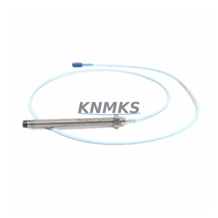
Bently Nevada 330101-00-40-10-02-00 Migration-Ready Proximity Transducer: Legacy System Migration and Compatible Upgrade
The Bently Nevada 330101-00-40-10-02-00 is a 3300 XL Series proximity transducer engineered for continuous shaft vibration and position monitoring in rotating machinery applications. As legacy 3300 Series installations approach end-of-support milestones and original transducer assemblies become increasingly difficult to source, the 330101-00-40-10-02-00 serves as the primary migration-ready replacement for discontinued proximity transducer variants across turbines, compressors, pumps, and gearboxes operating under API 670-compliant monitoring architectures.
This transducer is part of the 3300 XL proximity system, which operates as a three-component assembly: the transducer probe, the extension cable, and the proximitor/oscillator driver. When replacing a legacy 3300 Series transducer with the 330101-00-40-10-02-00, engineers must confirm that the existing extension cable — typically a 330130 or 330180 series — and the proximitor module, such as the 3300 XL 8mm proximitor, remain electrically matched to the new probe. Mismatched system components will produce calibration offsets and erroneous gap voltage readings, which can trigger false alarms or mask genuine rotor excursions in the vibration monitoring loop.
Before committing to a field swap, maintenance teams should verify the installed gap voltage at the proximitor output, typically targeting –10.0 VDC at the nominal 1.0 mm (40 mil) gap for 8 mm probe systems. The 330101-00-40-10-02-00 uses a standard –24 VDC supply rail, and the proximitor driver — often housed in a 3500/42M or 3500/40M monitor rack card — must be confirmed compatible with the probe’s sensitivity specification of 7.87 V/mm (200 mV/mil). If the existing rack is a legacy 3300 Series monitor rather than the 3500 Series, a parallel migration path involving the 3500 rack system should be evaluated to avoid signal chain incompatibilities.
Terminal wiring for the 330101-00-40-10-02-00 follows the standard Bently Nevada coaxial signal convention: the center conductor carries the –24 VDC bias and the RF oscillator signal, while the shield is grounded at the proximitor end only. Floating the shield at the transducer end is critical to prevent ground loop interference in high-noise industrial environments such as motor control centers or variable frequency drive (VFD) cabinets. When retrofitting into existing conduit runs, engineers should inspect the extension cable for jacket integrity and connector seating, as degraded coaxial connections are a leading cause of intermittent gap voltage drift in long-service installations.
For control system migrations involving a transition from a legacy DCS historian to a modern platform — such as moving from a Honeywell TDC 3000 or Emerson Ovation environment to a current-generation DCS — the 330101-00-40-10-02-00 output signal remains a standard –24 VDC analog loop compatible with most 4–20 mA signal conditioners and direct-connect monitor inputs. No firmware changes are required at the transducer level; however, the 3500 Series monitor rack may require a configuration download via System 1 software to update channel scaling, alert setpoints, and danger thresholds following a probe replacement. Backup the existing rack configuration before any field swap to preserve alarm logic and historical baseline data.
Installation space confirmation is essential in retrofit planning. The 330101-00-40-10-02-00 uses an 8 mm probe tip diameter with a standard 3/8–24 UNF mounting thread. Bearing housing access ports must be verified for thread compatibility and radial clearance before installation. In tight-clearance applications — common in older compressor trains with limited bearing bracket access — the probe body length and armored cable routing must be pre-planned to avoid mechanical interference with adjacent components such as thrust collar assemblies or lube oil supply lines.
Commissioning after replacement involves a systematic gap-setting procedure: with the shaft stationary, adjust the probe gap to achieve the target –10.0 VDC output, then confirm dynamic response by observing the 1X and 2X vibration amplitude and phase readings during a controlled run-up. Compare post-replacement baseline data against the pre-outage trend to confirm the new transducer is tracking correctly. Any deviation greater than 10% from the historical 1X amplitude baseline warrants further investigation before returning the machine to full load.
KNMKS maintains verified stock of the 330101-00-40-10-02-00 with pre-shipment functional testing, including gap voltage verification and coaxial connector integrity checks. Each unit ships with a support terms confirmed by quotation covering manufacturing defects and calibration conformance. Typical lead time from order confirmation to dispatch is 1–3 business days for in-stock units, supporting planned outage windows and emergency breakdown scenarios alike.
Migration Compatibility Table
| Parameter | 330101-00-40-10-02-00 (Replacement) | Legacy 3300 Series Transducer | Notes |
|---|---|---|---|
| Probe Diameter | 8 mm | 8 mm | Direct dimensional match |
| Mounting Thread | 3/8–24 UNF | 3/8–24 UNF | No housing modification required |
| Supply Voltage | –24 VDC | –24 VDC | Confirm proximitor rail voltage |
| Sensitivity | 7.87 V/mm (200 mV/mil) | 7.87 V/mm (200 mV/mil) | Verify monitor channel scaling |
| Gap Voltage (nominal) | –10.0 VDC @ 1.0 mm gap | –10.0 VDC @ 1.0 mm gap | Re-gap after installation |
| Extension Cable Compatibility | 330130 / 330180 Series | 330130 / 330180 Series | Inspect cable jacket and connectors |
| Proximitor Compatibility | 3300 XL 8mm Proximitor | 3300 XL 8mm Proximitor | Confirm driver model before swap |
| Monitor Rack Compatibility | 3500/40M, 3500/42M | 3300 Series Monitor | 3500 rack config download required |
| Communication Protocol | Analog –24 VDC / 4–20 mA compatible | Analog –24 VDC | No protocol migration required |
| Commissioning Tool | System 1 Software | 3300 Series Configurator | Backup config before replacement |
| Support terms | 12 Months | N/A (discontinued) | Covers calibration and manufacturing defects |
Retrofit Planning for Existing Automation Systems
A successful retrofit of the 330101-00-40-10-02-00 into an existing vibration monitoring loop requires a structured bill-of-materials review across the full signal chain. Beyond the transducer itself, the retrofit scope typically encompasses the 3300 XL 8mm proximitor driver, the 330130 series armored extension cable connecting the probe to the proximitor, and the 3500/40M or 3500/42M monitor rack card that processes the gap voltage signal and generates the 4–20 mA output to the DCS analog input card.
In installations where the existing 3300 Series monitor rack is also being retired, the migration path commonly involves a parallel installation of a 3500 Series rack system alongside the legacy hardware during a planned outage window. This approach allows the new rack to be pre-configured, loop-checked, and alarm-setpoint-verified before the legacy system is decommissioned, minimizing the risk of unmonitored machine operation during the transition period. The 3500 rack’s Modbus TCP or FOUNDATION Fieldbus communication module can be pre-wired to the plant DCS during this parallel phase, enabling historian data continuity without a hard cutover gap.
For plants operating Emerson DeltaV or Honeywell Experion PKS as the primary DCS, the 4–20 mA output from the 3500 monitor rack maps directly to standard AI card inputs without signal conditioning. However, if the legacy installation used a dedicated signal isolator — such as a DIN-rail-mounted galvanic isolator between the proximitor output and the DCS AI card — the isolator’s input impedance and loop power characteristics should be re-verified against the 3500 rack output specification to avoid loading errors that could shift the calibrated gap voltage reading.
HMI faceplate updates are a frequently overlooked element of proximity transducer retrofits. If the plant HMI — whether a Wonderware InTouch, FactoryTalk View, or Emerson DeltaV Operate screen — displays raw gap voltage or derived vibration amplitude in engineering units, the tag scaling parameters must be updated to reflect the new transducer’s calibration curve. Failure to update HMI scaling will result in displayed values that appear correct under normal operating conditions but diverge from actual shaft displacement during high-vibration events, potentially masking a developing fault condition.
Where I/O expansion is part of the broader control system upgrade, the addition of a 3500 Series rack provides an opportunity to consolidate multiple legacy 3300 Series monitoring loops onto a single rack platform, reducing panel space requirements and simplifying the maintenance spare-parts inventory. Each 3500/40M card supports up to four proximity transducer channels, allowing a four-probe bearing monitoring arrangement — typical for a two-bearing horizontal centrifugal pump — to be served by a single monitor card rather than the multiple single-channel 3300 Series modules it replaces.
Downtime Control During System Migration
Minimizing unplanned downtime during a proximity transducer replacement requires pre-staging all replacement components — the 330101-00-40-10-02-00 probe, the matched extension cable, and any required proximitor or monitor rack hardware — at the work site before the machine is taken offline. A pre-outage checklist should confirm that the replacement transducer has been bench-tested for gap voltage output, that the extension cable connectors are clean and undamaged, and that the System 1 configuration file for the 3500 rack has been backed up and is available for restoration if needed.
During the outage, the original program logic in the DCS — including vibration alarm setpoints, danger thresholds, and machine protection trip logic — should remain unchanged at the DCS level. The 3500 rack configuration is the only layer that requires updating, and this can be completed in under 30 minutes using a laptop running System 1 software connected to the rack’s Ethernet service port. Preserving the DCS logic layer intact ensures that the machine protection system returns to its pre-outage state immediately upon re-energization, without requiring a separate DCS engineering change order or management-of-change review.
For critical machinery where continuous monitoring is contractually required — such as API 670-protected compressors in LNG or refinery service — a temporary portable vibration monitoring system can be deployed on the adjacent bearing housing during the transducer swap to maintain surveillance on the machine train. This approach is particularly valuable in installations where the machine cannot be fully isolated and must remain in a hot-standby or slow-roll condition during the maintenance window.
Post-replacement commissioning should be completed before the machine is returned to full load. The gap-setting procedure, dynamic run-up verification, and a 30-minute steady-state observation period at normal operating speed are the minimum acceptance criteria before signing off the work order. Any anomalies in the 1X or 2X vibration trend during run-up — such as amplitude spikes at critical speed or unexpected phase shifts — should be investigated before load is applied, as these can indicate a probe installation error, a gap-setting deviation, or a pre-existing mechanical condition that the legacy transducer was masking due to calibration drift.
Retrofit Support FAQ
Q1: Is the 330101-00-40-10-02-00 a direct drop-in replacement for all legacy 3300 Series 8 mm proximity transducers?
The 330101-00-40-10-02-00 is dimensionally and electrically compatible with the standard 3300 XL 8 mm proximity system. However, engineers should confirm the specific legacy part number being replaced, as some early 3300 Series variants used different sensitivity specifications or connector types. KNMKS can assist with cross-reference verification before order placement.
Q2: What commissioning steps are required after installing the 330101-00-40-10-02-00?
After mechanical installation, set the probe gap to achieve –10.0 VDC output at the proximitor with the shaft stationary. Download the updated 3500 rack configuration via System 1 software if the monitor rack has been changed. Perform a controlled run-up and verify 1X vibration amplitude and phase against the pre-outage baseline. Document the new gap voltage and vibration baseline in the plant maintenance management system (CMMS) for future reference.
Q3: Can the existing 330130 extension cable be reused with the new transducer?
In most cases, yes — provided the cable jacket is intact, the coaxial connectors are clean and properly seated, and the cable length matches the proximitor’s calibrated range. A cable that has been kinked, crushed, or exposed to chemical contamination should be replaced with a new 330130 or 330180 series cable to avoid intermittent signal faults that are difficult to diagnose in the field.
Q4: What does the support terms confirmed by quotation cover, and what is the typical lead time?
The support terms confirmed by quotation cover manufacturing defects and calibration conformance verified against Bently Nevada factory specifications. Each unit undergoes pre-shipment gap voltage and coaxial integrity testing at KNMKS before dispatch. In-stock units typically ship within 1–3 business days. Emergency orders can be accommodated — contact the sales team directly to confirm availability and expedited dispatch options.
© 2026 KNMKS. All rights reserved.
Original Source: https://knmks.com
Contact: admin@knmks.com | +86 18359268345
Product Identification
- Brand / Ecosystem
-
Bently Nevada
Bently Nevada - Model / Series
-
330101-00-40-10-02-00
Bently Nevada 3300 XL / 3301 Series - Product Family
- Sensors
- Availability Status
- Available on request after model and quantity confirmation
- Inquiry Type
- B2B RFQ, replacement inquiry and project spare-part request
- Pre-Quote Check
- Exact SKU, brand, series, quantity, nameplate photos and destination country are checked before quotation
System Path
Where this product fits in the KNMKS automation structure.
Specification & Inquiry Focus
- Sensor range
- Photoelectric, proximity and process sensors
- Common needs
- Output type, distance and connector
- Project support
- Machine detection and replacement inquiry
Buyer Confirmation
Information KNMKS checks before replying.
- Exact model
- 330101-00-40-10-02-00
- Brand / ecosystem
- Bently Nevada
- Product family
- Sensors
- Application note
- Replacement, maintenance, project build or spare-part list
- Useful photos
- Nameplate, installed unit, cabinet layout or connector side
- Delivery details
- Quantity, destination country and target schedule
Document Support
Files and notes can be confirmed during quotation.
- Product photos or nameplate confirmation when available
- Packing and delivery notes before quotation confirmation
- Support scope and delivery terms confirmed per inquiry
- Export document coordination for qualified B2B requests
Inquiry Support
- NPN/PNP, analog and digital output checking
- Connector and cable compatibility review
- Fast inquiry support for maintenance teams
What to Send Us
- Brand and exact model number: Bently Nevada 330101-00-40-10-02-00
- Quantity and required delivery time
- Application, replacement requirement or nameplate photo
- Destination country and shipping preference
RFQ Preparation
This is a product inquiry page built for RFQ communication.
Fast Model Check
Send this model to KNMKS for confirmation.
Include quantity, destination country and photos if this is a maintenance replacement. The inquiry will be saved with a reference number after submission.
Brand & Compatibility Note
KNMKS displays automation product information for well-known industrial brand ecosystems and compatible replacement references. Brand names are used for product identification and compatibility reference only; final availability and commercial terms are confirmed per quotation.
 Manufacturing
 Machine Tools
 Packaging
 Energy & Power



 PLCs & Controllers
 HMI & Displays
 Servo Systems
 Variable Frequency Drives