
Overview
Bently Nevada 330101-00-20-05-02-00 Migration-Ready Proximity Transducer for Legacy Control Systems
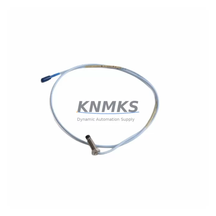
The Bently Nevada 330101-00-20-05-02-00 is an 8mm proximity transducer engineered for the 3300 XL Series continuous machinery monitoring platform. As legacy vibration monitoring systems reach end-of-life and OEM support windows close, this module has become a critical retrofit component for facilities managing aging turbomachinery, compressors, pumps, and rotating equipment across petrochemical, power generation, and heavy industrial environments. Whether you are replacing a failed unit on an emergency basis or executing a planned migration from an older 3300 Series rack to a modernized 3300 XL architecture, the 330101-00-20-05-02-00 provides a verified drop-in upgrade path with minimal re-engineering.
Before initiating any replacement, engineers should confirm the existing cable length and extension cable compatibility. The 330101-00-20-05-02-00 is rated for a 2-metre probe with a 5-metre extension cable, giving a total system length of 7 metres. If the installed system uses a different total cable length — for example, a configuration previously paired with the 330130-080-00-00 extension cable — the gap and sensitivity calibration must be re-verified at commissioning. The output sensitivity of 7.87 V/mm (200 mV/mil) must match the input channel configuration of the 3300 XL monitor rack, particularly when the rack includes a 3300/16 or 3300/20 monitor card that was originally calibrated for an earlier transducer generation.
Terminal wiring during retrofit requires careful attention. The 330101-00-20-05-02-00 uses a standard Bently Nevada coaxial connector interface. When migrating from an older 330100 Series transducer, technicians should inspect the field junction box for any corrosion on the BNC or MIL-C connector terminations and replace as needed. The driver/extension cable — typically a 330130 Series or 330180 Series cable — must be confirmed compatible with the new probe before energizing the loop. Incorrect cable pairing is one of the most common causes of calibration drift and false alarm events during post-retrofit commissioning.
For facilities upgrading an entire monitoring rack, the 330101-00-20-05-02-00 is frequently deployed alongside the 3300 XL 8mm Proximitor Sensor driver, the 3300/16 Dual Voting Logic monitor, and the 3500/42M Proximitor/Seismic Monitor module in mixed-generation control cabinets. When the control system also includes a 3500 Series rack for critical machinery protection, engineers must verify that the Keyphasor signal routing between the 3300 XL and 3500 rack is correctly mapped, as Keyphasor phase reference inputs differ between the two platforms. Failure to align Keyphasor assignments will result in incorrect speed and phase readings on the HMI display, requiring a full re-mapping of the dynamic data manager (DDM) configuration.
Program compatibility is another key consideration. If the existing System 1 Condition Monitoring software is configured with transducer-specific calibration tables for the outgoing unit, those tables must be updated to reflect the 330101-00-20-05-02-00 sensitivity and gap voltage parameters. In installations where the HMI screens are built on a GE Mark VIe or Emerson Ovation DCS platform, the analog input scaling blocks tied to the proximity channel must be reviewed and adjusted to prevent nuisance trips during the first hours of operation after replacement.
Migration Compatibility Table
| Parameter | Detail |
|---|---|
| SKU / Part Number | 330101-00-20-05-02-00 |
| Brand / Series | Bently Nevada / 3300 XL Series |
| Probe Diameter | 8mm |
| Probe Length | 2 metres (standard) |
| Extension Cable Compatibility | 330130 Series / 330180 Series (5m standard) |
| Output Sensitivity | 7.87 V/mm (200 mV/mil) |
| Supply Voltage | -24 VDC (nominal) |
| Connector Interface | Coaxial / BNC / MIL-C (field junction box) |
| Mounting / Installation Space | Standard 3300 XL rack slot; confirm bracket clearance for 8mm tip |
| Communication / Signal Type | Analog voltage output (eddy-current proximity) |
| Replacement for | 330101 Series (earlier revisions), 330100 Series probes |
| Monitor Rack Compatibility | 3300 XL, 3300/16, 3300/20, 3500/42M (with driver verification) |
| Commissioning Requirement | Gap voltage calibration, sensitivity verification, HMI scaling review |
| Firmware / Software | System 1 calibration table update required if replacing earlier revision |
| Support terms | 12 Months from date of shipment |
| Stock Status | availability confirmed by RFQ — Ready to Ship |
Retrofit Planning for Existing Automation Systems
A successful retrofit begins well before the replacement unit arrives on site. For the 330101-00-20-05-02-00, the pre-installation checklist should include a review of the existing rack power supply capacity. The 3300 XL rack power supply — often a dedicated 3300 XL Power Supply module — must have sufficient headroom to support the transducer loop current after any additional I/O or monitor cards have been added during the upgrade cycle. If the rack has been expanded with additional 3300/16 Dual Voting Logic cards or a new 3300/20 monitor to cover additional measurement points, the total current draw must be recalculated against the power supply rating before energizing the new transducer.
Backplane interface integrity is equally important. In older 3300 XL racks that have been in service for more than ten years, the backplane connector pins may show signs of oxidation or micro-fretting, particularly in high-vibration environments. Before inserting the 330101-00-20-05-02-00 driver module, inspect the backplane slot for pin damage and clean contact surfaces with an approved contact cleaner. This step is frequently overlooked during emergency replacements and is a leading cause of intermittent signal faults in the weeks following a retrofit.
For facilities that are simultaneously upgrading their communication infrastructure — for example, migrating from a legacy Modbus RTU link to a FOUNDATION Fieldbus or OPC-UA architecture — the proximity monitoring data path must be re-mapped in the historian and DCS configuration. The 3300 XL system outputs analog signals that are typically wired to a 3500 rack or directly to a DCS analog input card. If the DCS is being replaced or upgraded as part of the same project, coordinate the signal handoff carefully to avoid a gap in machinery protection coverage during the cutover window.
I/O expansion during the same maintenance window is common. If the plant is adding new measurement points — for example, adding axial position monitoring with a second 330101-00-20-05-02-00 channel or installing a 330780 Velomitor accelerometer for high-frequency bearing monitoring — plan the cable routing and junction box assignments before the shutdown begins. Sharing a single maintenance window across multiple transducer replacements and I/O additions significantly reduces total downtime compared to executing each change in a separate outage.
Downtime Control During System Migration
Minimizing downtime during a proximity transducer replacement requires a structured approach to pre-staging, bypass management, and post-installation verification. Before the unit is removed, capture a full screenshot or data export of the current gap voltage, direct (DC) gap reading, and dynamic (AC) vibration amplitude from the System 1 or DCS historian. These baseline values serve as the acceptance criteria for the post-installation functional test and allow the commissioning engineer to confirm that the new 330101-00-20-05-02-00 is performing within the expected range before the machinery is returned to service.
Where the process cannot be fully shut down, a temporary bypass of the voting logic in the 3300/16 or 3300/20 monitor card may be required to prevent a spurious trip during the transducer swap. This bypass must be formally authorized under the plant’s management of change (MOC) procedure and should be time-limited to the minimum duration required for the physical replacement and initial gap setting. The bypass status must be clearly communicated to the control room operator and logged in the shift record.
Once the 330101-00-20-05-02-00 is installed and the extension cable is reconnected, the gap voltage should be set to the target value specified in the original installation drawing — typically between -10 VDC and -18 VDC for an 8mm probe, with the exact target depending on the target gap distance and the material of the observed surface. After gap setting, verify the dynamic output by observing the vibration amplitude on the monitor card or DCS display while the machine is at rest and then at operating speed. Confirm that the overall vibration reading is within the expected baseline range before releasing the bypass and returning the protection system to normal operation.
All commissioning steps — gap voltage measurement, sensitivity verification, alarm setpoint confirmation, and bypass release — should be documented in the plant’s maintenance management system (CMMS) with the replacement unit’s serial number and the date of installation. This documentation supports the support terms confirmed by quotation claim process and provides traceability for future maintenance planning.
Retrofit Support FAQ
Q: Is the 330101-00-20-05-02-00 a direct drop-in replacement for earlier 330101 revisions?
A: In most cases, yes. The 330101-00-20-05-02-00 is backward compatible with earlier 330101 Series revisions when used with the same cable length and driver configuration. However, if the installed system uses a non-standard cable length or an older 330100 Series probe, a full calibration verification is required after installation. We recommend confirming the total system length and sensitivity against the original installation drawing before ordering.
Q: What pre-shipment testing is performed on the 330101-00-20-05-02-00?
A: Every unit shipped by KNMKS undergoes a functional output test to verify sensitivity, gap voltage linearity, and connector integrity before dispatch. A test report is available upon request. Units are shipped in anti-static packaging with protective end caps to prevent tip damage during transit.
Q: Can this transducer be used with a 3500 Series rack instead of a 3300 XL rack?
A: The 330101-00-20-05-02-00 is designed for the 3300 XL platform. Use with a 3500/42M Proximitor/Seismic Monitor is possible in some configurations, but requires verification of the driver compatibility and input channel scaling. Contact our technical team at admin@knmks.com to confirm compatibility for your specific rack configuration before ordering.
Q: What is the support terms coverage and what does it include?
A: All units carry a support terms confirmed by quotation from the date of shipment, covering manufacturing defects and functional failures under normal operating conditions. The support terms does not cover damage resulting from incorrect installation, improper gap setting, or use outside the specified supply voltage range. In the event of a support terms claim, KNMKS will arrange for a replacement unit to be dispatched upon receipt and inspection of the returned item.
© 2026 KNMKS. All rights reserved.
Original Source: https://knmks.com
Contact: admin@knmks.com | +86 18359268345
Product Identification
- Brand / Ecosystem
-
Bently Nevada
Bently Nevada - Model / Series
-
330101-00-20-05-02-00
Bently Nevada 3300 XL / 3301 Series - Product Family
- Sensors
- Availability Status
- Available on request after model and quantity confirmation
- Inquiry Type
- B2B RFQ, replacement inquiry and project spare-part request
- Pre-Quote Check
- Exact SKU, brand, series, quantity, nameplate photos and destination country are checked before quotation
System Path
Where this product fits in the KNMKS automation structure.
Specification & Inquiry Focus
- Sensor range
- Photoelectric, proximity and process sensors
- Common needs
- Output type, distance and connector
- Project support
- Machine detection and replacement inquiry
Buyer Confirmation
Information KNMKS checks before replying.
- Exact model
- 330101-00-20-05-02-00
- Brand / ecosystem
- Bently Nevada
- Product family
- Sensors
- Application note
- Replacement, maintenance, project build or spare-part list
- Useful photos
- Nameplate, installed unit, cabinet layout or connector side
- Delivery details
- Quantity, destination country and target schedule
Document Support
Files and notes can be confirmed during quotation.
- Product photos or nameplate confirmation when available
- Packing and delivery notes before quotation confirmation
- Support scope and delivery terms confirmed per inquiry
- Export document coordination for qualified B2B requests
Inquiry Support
- NPN/PNP, analog and digital output checking
- Connector and cable compatibility review
- Fast inquiry support for maintenance teams
What to Send Us
- Brand and exact model number: Bently Nevada 330101-00-20-05-02-00
- Quantity and required delivery time
- Application, replacement requirement or nameplate photo
- Destination country and shipping preference
RFQ Preparation
This is a product inquiry page built for RFQ communication.
Fast Model Check
Send this model to KNMKS for confirmation.
Include quantity, destination country and photos if this is a maintenance replacement. The inquiry will be saved with a reference number after submission.
Brand & Compatibility Note
KNMKS displays automation product information for well-known industrial brand ecosystems and compatible replacement references. Brand names are used for product identification and compatibility reference only; final availability and commercial terms are confirmed per quotation.
 Manufacturing
 Machine Tools
 Packaging
 Energy & Power



 PLCs & Controllers
 HMI & Displays
 Servo Systems
 Variable Frequency Drives