
Overview
Bently Nevada 330101-00-18-10-12-05 Migration-Ready Proximity Transducer for Legacy Control Systems
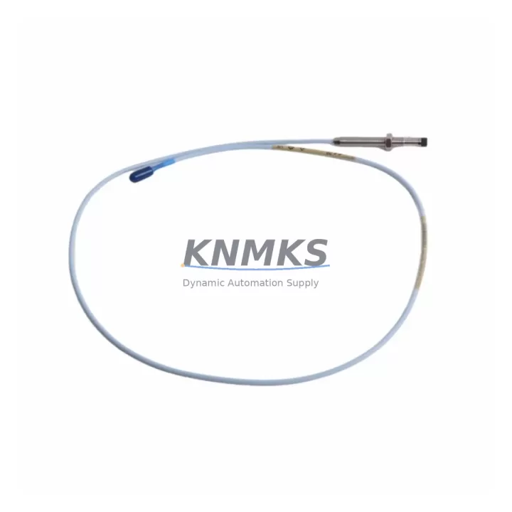
The Bently Nevada 330101-00-18-10-12-05 is an 8mm eddy-current proximity transducer engineered for the 3300 XL Series condition monitoring platform. As rotating machinery protection systems age and OEM support windows close, plant engineers face increasing pressure to source verified replacement components that maintain signal integrity, wiring compatibility, and firmware alignment with existing monitor racks. This unit is stocked, pre-tested, and ready for immediate deployment as a direct retrofit replacement for legacy 3300 XL installations where the original transducer has reached end-of-life or is no longer available through standard distribution channels.
The 330101-00-18-10-12-05 operates on the standard Bently Nevada proximity system principle: the transducer, extension cable, and proximitor/driver form a complete measurement chain. When retrofitting, engineers must confirm that the replacement transducer is matched to the correct proximitor model — typically the 3300 XL 8mm Proximitor — to maintain the calibrated output range of -24 VDC at the gap center. Mismatched transducer-proximitor pairs are a leading cause of calibration drift and false trips during post-retrofit commissioning. All units supplied by KNMKS are verified against OEM calibration specifications prior to shipment.
For legacy panel upgrades where the original 330101-series transducer is being replaced alongside monitor card refreshes, it is common to simultaneously address the 3300/16-24-01 Dual Voting Logic Monitor or the 3500/42M Proximitor/Seismic Monitor Module, both of which share the same rack infrastructure and signal conditioning architecture. Ensuring that the new transducer’s output voltage curve aligns with the monitor card’s input threshold settings eliminates the need for software recalibration of trip and alarm setpoints — a critical time-saving step during planned outage windows.
Terminal wiring on the 330101-00-18-10-12-05 follows the standard Bently Nevada three-wire convention: power supply (–24 VDC), signal output, and common/shield. Before disconnecting the legacy transducer, technicians should document the existing terminal assignments on the field junction box and the monitor rack I/O terminal strip. Where extension cables such as the 330130-080-00-00 are in use, inspect the cable connectors for corrosion or mechanical damage — extension cable degradation is frequently misdiagnosed as transducer failure in high-vibration environments. Replacing the transducer without inspecting the extension cable can result in repeat failures within the first operational cycle.
Backplane and rack slot compatibility should be confirmed before installation. The 3300 XL rack accepts standard 3300-series monitor cards, and the transducer connects to the field wiring terminal block rather than directly to the backplane. However, if the retrofit is part of a broader migration from a 3300 XL rack to a 3500 Series rack, the physical mounting footprint, terminal block pinout, and monitor card firmware version must all be re-evaluated. The 3500 Series uses a different I/O module architecture, and direct transducer substitution without rack-level planning can introduce ground loop issues or impedance mismatches that affect measurement accuracy.
HMI screen updates are often overlooked during transducer retrofits. If the plant DCS or SCADA system displays vibration trend data sourced from the Bently Nevada monitor rack via a 3500/92 Communication Gateway Module or a direct Modbus/TCP link, the engineering team should verify that the tag mapping and EU (engineering unit) scaling remain consistent after the replacement. A transducer swap that shifts the gap voltage by even a small margin can cause the HMI trend to display a step-change in the vibration baseline, triggering unnecessary operator intervention or masking a genuine machinery fault.
Firmware compatibility is particularly relevant when the 330101-00-18-10-12-05 is being installed into a rack that has been partially upgraded. Mixed firmware environments — where some monitor cards have been updated to current revision while others remain on legacy firmware — can produce inconsistent behavior in the voting logic and system status outputs. KNMKS recommends that customers confirm the firmware revision of the target monitor card before dispatch so that any known compatibility advisories can be addressed prior to installation.
Installation space confirmation is straightforward for standard 3300 XL installations: the 8mm transducer body diameter and the standard armored cable routing are unchanged from the original specification. However, in retrofitted control cabinets where cable management has been modified or where additional I/O modules such as the 3300/55 Temperature Monitor have been added to the rack, cable bend radius and connector clearance should be physically verified before the outage begins. Inadequate clearance around the transducer connector is a common source of installation delay during time-critical shutdowns.
KNMKS maintains ready stock of the 330101-00-18-10-12-05 to support emergency replacement, planned maintenance, and long-term spare parts programs. Each unit ships with a support terms confirmed by quotation covering manufacturing defects and calibration conformance. Pre-shipment functional testing is performed on every unit, and a test report is available upon request for customers with quality management system documentation requirements.
Migration Compatibility Table
| Parameter | 330101-00-18-10-12-05 (This Unit) | Legacy / Notes |
|---|---|---|
| Transducer Diameter | 8mm | Direct fit for standard 3300 XL 8mm mounting bosses |
| Cable Length (Transducer) | 5m (integral) | Extend with 330130-series extension cable as required |
| Output Voltage Range | –24 VDC system (–2 to –18 VDC signal) | Must match 3300 XL 8mm Proximitor input specification |
| Terminal Wiring | 3-wire: –24V, Signal, Common/Shield | Verify field junction box terminal assignments before swap |
| Rack Compatibility | 3300 XL Series rack | 3500 Series rack requires re-evaluation of I/O architecture |
| Monitor Card Pairing | 3300 XL 8mm Proximitor Monitor | Confirm monitor card firmware revision before installation |
| Communication Interface | Analog signal to monitor rack | Digital output via 3500/92 Gateway (Modbus/TCP, etc.) |
| HMI / SCADA Impact | Verify EU scaling and tag mapping post-swap | Step-change in baseline may trigger false alarms |
| Installation Space | Standard 8mm body, armored cable | Confirm clearance in modified or upgraded cabinets |
| Firmware Compatibility | Confirm monitor card firmware revision | Mixed firmware environments may cause voting logic issues |
| Support terms | 12 Months | Covers manufacturing defects and calibration conformance |
| Pre-Shipment Testing | Yes — functional test report available | Request documentation for QMS compliance |
Retrofit Planning for Existing Automation Systems
Successful retrofit of the 330101-00-18-10-12-05 into an existing automation system requires a structured pre-outage planning process that addresses every component in the measurement chain and the broader control architecture. The transducer itself is only one element of a system that includes the extension cable, the proximitor/driver, the monitor card, the rack power supply, the communication gateway, and the HMI or DCS integration layer.
Begin by auditing the existing 3300 XL rack configuration. Identify all occupied slots, confirm the power supply module capacity — typically the 3300/05 Power Supply — and verify that the rack can support the current draw of all installed monitor cards plus any new modules being added as part of the broader upgrade. Undersized power supply modules are a frequent source of intermittent faults in partially upgraded racks, particularly when higher-density I/O modules or additional communication cards have been added since the original installation.
The extension cable connecting the 330101-00-18-10-12-05 to the proximitor is a critical and often underestimated component. The 330130-series extension cables are available in standard lengths and must be selected to match the total system cable length specification for the 8mm transducer system. Exceeding the maximum cable length degrades the eddy-current field and shifts the calibration curve, producing measurement errors that may not be immediately apparent during initial commissioning but will manifest as drift over time.
For plants migrating from older 3300-series racks to the 3500 Series platform, the 3500/20 Rack Interface I/O Module and the 3500/92 Communication Gateway Module are typically involved in the integration layer. The communication gateway supports multiple protocols including Modbus RTU, Modbus TCP/IP, and Ethernet/IP, and its configuration must be updated to reflect any changes in channel assignments or monitor card slot positions resulting from the retrofit. Failure to update the gateway configuration is a common cause of data mapping errors in the DCS historian following a rack upgrade.
Where the retrofit is part of a control cabinet modernization that also involves PLC or safety system upgrades, signal isolation between the Bently Nevada monitor outputs and the PLC analog input modules should be verified. Signal isolators or barriers may be required to prevent ground loops, particularly in installations where the monitor rack and the PLC cabinet share a common instrument earth but are located in different physical enclosures. Addressing grounding architecture during the planning phase avoids costly rework during commissioning.
Programming cable access for monitor card configuration — typically via the Bently Nevada 3500 Configuration Software and a standard RS-232 or USB-to-serial adapter — should be confirmed as part of the pre-outage checklist. Configuration backups of all monitor cards should be taken before any hardware changes are made, ensuring that the original setpoints, alarm thresholds, and trip logic can be restored if required.
Downtime Control During System Migration
Minimizing downtime during a proximity transducer retrofit requires disciplined pre-outage preparation, clear task sequencing, and a verified rollback plan. The 330101-00-18-10-12-05 is designed as a direct replacement for the original 3300 XL 8mm transducer, which means that — under normal circumstances — the physical installation, wiring termination, and gap setting can be completed within a standard planned maintenance window without requiring monitor card reconfiguration or DCS engineering changes.
The most effective downtime reduction strategy is to complete all preparatory work before the machinery is taken offline. This includes: confirming the replacement transducer calibration certificate, documenting the existing gap voltage at the current operating clearance, photographing the terminal wiring at the field junction box and the monitor rack, and verifying that the extension cable and proximitor are in serviceable condition. When these steps are completed in advance, the actual on-machine installation time is reduced to the physical swap, gap setting, and signal verification — typically less than two hours for a single measurement point.
Protecting the original program logic and control configuration is equally important. Before the outage begins, export and archive the current monitor card configuration using the Bently Nevada configuration software. If the retrofit is part of a broader rack upgrade that involves replacing monitor cards or adding new modules, ensure that the rack configuration file is updated and validated in a test environment before being loaded to the live system. Loading an untested configuration to a live rack during a time-critical outage is a significant risk that can extend downtime by hours.
Maintaining field control continuity during the swap requires coordination with the control room. The monitor channel being serviced should be placed in bypass mode — where the system architecture supports it — to prevent a false trip from interrupting adjacent machinery or triggering a plant-wide safety response. After the new transducer is installed and the gap is set, the channel should be returned to normal monitoring mode only after the signal output has been verified against the expected voltage range at the operating clearance.
Post-installation verification should include a slow-roll check of the machinery to confirm that the vibration signal is tracking correctly and that the trend data appearing on the HMI or DCS is consistent with the pre-outage baseline. Any step-change in the vibration baseline that cannot be explained by a change in machinery condition should be investigated before the unit is returned to full-speed operation. KNMKS provides post-shipment technical support to assist with commissioning questions and signal verification during the retrofit process.
Retrofit Support FAQ
Q1: Is the 330101-00-18-10-12-05 a direct drop-in replacement for the original Bently Nevada unit?
Yes. The 330101-00-18-10-12-05 is manufactured to the original Bently Nevada specification and is a direct physical and electrical replacement for the original unit in 3300 XL Series installations. No monitor card reconfiguration is required provided the replacement transducer is paired with the correct 3300 XL 8mm Proximitor and the total system cable length remains within specification.
Q2: What pre-shipment testing is performed, and is documentation available?
Every unit undergoes functional testing prior to shipment, including verification of the output voltage curve against the OEM calibration specification. A test report is available upon request and is suitable for inclusion in quality management system records. Units are shipped with a support terms confirmed by quotation covering manufacturing defects and calibration conformance.
Q3: How do I confirm wiring compatibility before installation?
The 330101-00-18-10-12-05 uses the standard Bently Nevada three-wire connection: –24 VDC supply, signal output, and common/shield. Before disconnecting the legacy transducer, document the existing terminal assignments at the field junction box and the monitor rack terminal strip. If the installation uses a 330130-series extension cable, inspect the cable connectors for corrosion or mechanical damage and confirm that the total cable length does not exceed the system specification for the 8mm transducer.
Q4: What is the lead time and support terms coverage?
The 330101-00-18-10-12-05 is maintained in ready stock at KNMKS to support both emergency replacement and planned maintenance programs. Standard lead time for in-stock units is 1–3 business days for international shipment. All units are covered by a support terms confirmed by quotation from the date of shipment. For large-quantity orders or long-term spare parts agreements, contact the KNMKS sales team to discuss pricing and availability.
© 2026 KNMKS. All rights reserved.
Original Source: https://knmks.com
Contact: admin@knmks.com | +86 18359268345
Product Identification
- Brand / Ecosystem
-
Bently Nevada
Bently Nevada - Model / Series
-
330101-00-18-10-12-05
Bently Nevada 3300 XL / 3301 Series - Product Family
- Sensors
- Availability Status
- Available on request after model and quantity confirmation
- Inquiry Type
- B2B RFQ, replacement inquiry and project spare-part request
- Pre-Quote Check
- Exact SKU, brand, series, quantity, nameplate photos and destination country are checked before quotation
System Path
Where this product fits in the KNMKS automation structure.
Specification & Inquiry Focus
- Sensor range
- Photoelectric, proximity and process sensors
- Common needs
- Output type, distance and connector
- Project support
- Machine detection and replacement inquiry
Buyer Confirmation
Information KNMKS checks before replying.
- Exact model
- 330101-00-18-10-12-05
- Brand / ecosystem
- Bently Nevada
- Product family
- Sensors
- Application note
- Replacement, maintenance, project build or spare-part list
- Useful photos
- Nameplate, installed unit, cabinet layout or connector side
- Delivery details
- Quantity, destination country and target schedule
Document Support
Files and notes can be confirmed during quotation.
- Product photos or nameplate confirmation when available
- Packing and delivery notes before quotation confirmation
- Support scope and delivery terms confirmed per inquiry
- Export document coordination for qualified B2B requests
Inquiry Support
- NPN/PNP, analog and digital output checking
- Connector and cable compatibility review
- Fast inquiry support for maintenance teams
What to Send Us
- Brand and exact model number: Bently Nevada 330101-00-18-10-12-05
- Quantity and required delivery time
- Application, replacement requirement or nameplate photo
- Destination country and shipping preference
RFQ Preparation
This is a product inquiry page built for RFQ communication.
Fast Model Check
Send this model to KNMKS for confirmation.
Include quantity, destination country and photos if this is a maintenance replacement. The inquiry will be saved with a reference number after submission.
Brand & Compatibility Note
KNMKS displays automation product information for well-known industrial brand ecosystems and compatible replacement references. Brand names are used for product identification and compatibility reference only; final availability and commercial terms are confirmed per quotation.
 Manufacturing
 Machine Tools
 Packaging
 Energy & Power



 PLCs & Controllers
 HMI & Displays
 Servo Systems
 Variable Frequency Drives