
Overview
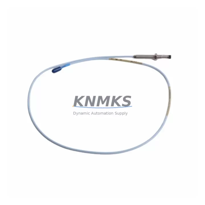
Bently Nevada 330101-00-11-15-12-CN Migration-Ready Proximity Transducer for Legacy Control Systems
The Bently Nevada 330101-00-11-15-12-CN is an 8mm eddy-current proximity transducer engineered for the 3300 XL Series vibration monitoring platform. As legacy machinery protection systems approach end-of-life and OEM support windows close, this transducer serves as a verified drop-in replacement for discontinued 330101-series components, enabling engineers to extend the operational life of existing monitor racks, field wiring, and control cabinets without a full platform overhaul.
Whether you are restoring a turbine protection loop, replacing a failed shaft-sensing channel, or executing a phased migration from an older Bently Nevada 3300 rack to a modern System 1 condition monitoring architecture, the 330101-00-11-15-12-CN delivers the dimensional, electrical, and signal-chain compatibility required to minimize engineering rework and reduce unplanned downtime.
Migration Compatibility Table
| Parameter | 330101-00-11-15-12-CN Specification | Retrofit / Migration Notes |
|---|---|---|
| Probe Diameter | 8 mm | Direct fit for existing 8 mm bore installations; no re-machining required |
| Cable Length | 1.0 m probe + extension cable | Verify total system cable length matches driver calibration range (typically 5 m or 9 m system) |
| Thread | M10 x 1.0 | Confirm bracket thread before installation; no adapter required for standard 3300 XL brackets |
| Gap Voltage Range | -10 VDC to -18 VDC | Set gap to -10 V +/- 0.5 V at nominal 1.0 mm air gap; re-verify after installation |
| Signal Output | 200 mV/mil (7.87 V/mm) | Compatible with 3300 XL monitor input cards; no scale-factor reprogramming needed |
| Power Supply | -24 VDC (via driver/extension) | Confirm rack power supply capacity when adding channels; typical 3300 XL PSU supports up to 16 channels |
| Driver Compatibility | 330130 / 330180 series drivers | Pair with Bently Nevada 330130-040-00-00 or 330180-X1-05 driver; verify driver firmware revision |
| Monitor Card Interface | 3300 XL 16-channel monitor | Slot assignment and channel address must match original configuration in System 1 software |
| Installation Space | Standard 3300 XL rack slot | No additional DIN rail or panel cutout required; confirm backplane connector seating |
| Communication Protocol | Analog (4-20 mA / voltage) + RS-232/RS-485 via monitor | For Modbus or OPC-UA migration, protocol conversion is handled at the monitor or gateway level, not the transducer |
| Firmware / Calibration | Factory calibrated; no field firmware | Re-run gap calibration procedure after installation; update System 1 channel configuration if replacing a different SKU |
| Support terms | support terms confirmed by quotation – covers manufacturing defects; includes pre-shipment functional test report | |
Retrofit Planning for Existing Automation Systems
Successful integration of the 330101-00-11-15-12-CN into a legacy protection system begins well before the transducer arrives on site. A structured retrofit plan should address the following areas:
Power Budget Verification: Before adding or replacing transducer channels, audit the existing rack power supply. A standard Bently Nevada 3300 XL power supply module (e.g., 3300/20) delivers regulated -24 VDC to all installed driver/extension assemblies. When migrating from a partial rack to a fully populated 16-channel configuration, confirm that the PSU current capacity is not exceeded. If the existing PSU is marginal, a redundant power supply module should be installed before commissioning the new transducer channels.
Terminal Wiring and Extension Cable Routing: The 330101-00-11-15-12-CN ships with a 1.0 m armored probe cable terminated in a standard BNC-style connector. In most field installations, this connects to a Bently Nevada 330130 series extension cable, which routes signal back to the driver mounted in the control cabinet. Inspect existing extension cables for insulation damage, connector corrosion, and shield continuity before reuse. Replace any extension cable showing impedance drift, as this will shift the gap voltage calibration and trigger false alerts.
Backplane and Rack Interface: The 3300 XL monitor rack uses a passive backplane to distribute power and route analog signals from driver outputs to monitor input cards. When replacing a transducer on an active rack, confirm that the corresponding 3300 XL monitor card (e.g., 3300/25 or 3300/46 dual-channel monitor) is seated correctly and that the backplane connector shows no signs of fretting corrosion, a common failure mode in high-vibration environments.
Module Address and Channel Configuration: Each transducer channel in the 3300 XL system is assigned a logical address within the System 1 condition monitoring software. When swapping a 330101-series transducer for the 330101-00-11-15-12-CN, the channel address, engineering unit scaling, and alarm setpoints should be verified against the original configuration file. If the replacement SKU differs in sensitivity or cable length from the original, the scale factor in System 1 must be updated before the channel is returned to service.
HMI Screen and Trend Data Continuity: Operators relying on vibration trend displays, whether through a dedicated Bently Nevada System 1 workstation or a third-party SCADA/DCS HMI, should verify that channel tag names and engineering unit assignments are preserved after the swap. A mismatch between the physical channel and the HMI tag will cause trend data gaps and may suppress alarm annunciation during the critical post-installation monitoring period.
Communication Link Integrity: In systems where the 3300 XL rack communicates upstream via Modbus RTU over RS-485 or through a GE/Baker Hughes System 1 gateway, verify that the communication link remains active throughout the transducer replacement. If the monitor card must be powered down for installation, coordinate with the control room to place the affected channels in bypass mode and notify the DCS operator to suppress spurious alarms during the maintenance window.
Signal Isolation and Grounding: In mixed-signal control cabinets where the 3300 XL rack shares an enclosure with PLC I/O modules, VFD drives, or relay output cards, ground loop interference can corrupt proximity transducer signals. If noise is observed on the gap voltage after installation, insert a signal isolator module between the driver output and the monitor input, or verify that the cable shield is grounded at one end only per Bently Nevada field wiring guidelines.
Downtime Control During System Migration
Minimizing production interruption during a transducer replacement requires a disciplined sequence of pre-work, execution, and post-installation verification steps.
Pre-Shutdown Preparation: Before the maintenance window opens, gather the original gap calibration records, the System 1 channel configuration export, and the as-built wiring diagram for the affected machine train. Confirm that a spare 330130 series extension cable and a calibrated gap-setting tool are available on site. Pre-stage the 330101-00-11-15-12-CN in the control room environment for at least two hours to allow thermal stabilization before installation.
Program Logic Protection: If the machine protection system is interlocked with a PLC or DCS, for example a GE Fanuc Series 90 controller or a Siemens S7-300 safety module, place the affected interlock in bypass mode using the approved management-of-change procedure before disconnecting the transducer. Document the bypass start time and assign a dedicated technician to monitor the machine manually during the replacement window. This preserves the original ladder logic and function block program without modification.
Hot-Swap Considerations: The 3300 XL architecture supports online card replacement for monitor cards, but transducer replacement at the probe tip requires physical access to the machine and typically a brief shutdown of the rotating equipment. Plan the replacement during a scheduled maintenance outage or coordinate with operations to use a planned process hold. Avoid transducer replacement during load transitions, as shaft position changes during installation can make gap setting unreliable.
Post-Installation Verification Sequence: After installation, follow this sequence to restore the channel to service with confidence: (1) Measure gap voltage at the driver output and confirm it falls within the -10 V +/- 0.5 V acceptance window. (2) Verify extension cable shield continuity and connector seating. (3) Confirm System 1 channel status shows OK with no fault flags. (4) Review the first 15 minutes of trend data to confirm signal noise floor is within specification. (5) Remove the interlock bypass and return the machine to normal protection. (6) Archive the post-installation gap calibration record for the equipment history file.
Firmware and Software Version Control: If the replacement is part of a broader migration from an older 3300 rack to a current-generation monitor platform, confirm that the System 1 software version supports the new monitor card firmware. Mismatched firmware versions between the monitor card and the System 1 server can cause communication dropouts that are difficult to distinguish from transducer faults during the initial post-installation period.
Retrofit Support FAQ
Q1: Is the 330101-00-11-15-12-CN a direct replacement for other 330101-series SKUs such as the 330101-00-11-10-02-00?
A: The 330101-00-11-15-12-CN shares the same 8 mm probe diameter and 200 mV/mil sensitivity as other 330101-series variants, but differs in cable length and connector configuration. Before substituting, verify that the total system cable length (probe + extension) matches the driver calibration range specified on the driver label. If the cable length differs, the driver must be recalibrated or replaced with a matching 330130 series driver configured for the new system length. Contact our technical team with your existing SKU and system cable length for a confirmed compatibility assessment.
Q2: What pre-shipment testing is performed, and what documentation is included?
A: Every 330101-00-11-15-12-CN unit undergoes a functional output test and dimensional inspection before shipment. A test report confirming gap voltage linearity and sensitivity is included with each unit. Units are shipped in anti-static packaging with a calibration certificate traceable to the original Bently Nevada factory specification. The support terms confirmed by quotation period begins from the date of shipment and covers manufacturing defects under normal operating conditions.
Q3: How do I confirm wiring compatibility with my existing control cabinet before ordering?
A: Locate the existing driver label in your control cabinet and note the system cable length designation (typically 5 m or 9 m). Cross-reference this with the probe cable length of the 330101-00-11-15-12-CN (1.0 m probe + extension). Confirm that the extension cable connector type matches the driver input. If your cabinet uses a 330180 series driver rather than a 330130, verify the driver compatible probe list before installation. Our team can review your wiring diagram and provide a compatibility confirmation prior to order placement.
Q4: What is your inventory availability and lead time for the 330101-00-11-15-12-CN?
A: We maintain in-stock inventory of the 330101-00-11-15-12-CN to support urgent replacement and planned maintenance schedules. Standard orders ship within 1-3 business days. For large-quantity orders or scheduled outage kitting (including matched extension cables, drivers, and monitor cards), contact our sales team to arrange a dedicated inventory reservation. All units are covered by a support terms confirmed by quotation from shipment date.
© 2026 KNMKS. All rights reserved.
Original Source: https://knmks.com
Contact: admin@knmks.com | +86 18359268345
Product Identification
- Brand / Ecosystem
-
Bently Nevada
Bently Nevada - Model / Series
-
330101-00-11-15-12-CN
Bently Nevada 3300 XL / 3301 Series - Product Family
- Sensors
- Availability Status
- Available on request after model and quantity confirmation
- Inquiry Type
- B2B RFQ, replacement inquiry and project spare-part request
- Pre-Quote Check
- Exact SKU, brand, series, quantity, nameplate photos and destination country are checked before quotation
System Path
Where this product fits in the KNMKS automation structure.
Specification & Inquiry Focus
- Sensor range
- Photoelectric, proximity and process sensors
- Common needs
- Output type, distance and connector
- Project support
- Machine detection and replacement inquiry
Buyer Confirmation
Information KNMKS checks before replying.
- Exact model
- 330101-00-11-15-12-CN
- Brand / ecosystem
- Bently Nevada
- Product family
- Sensors
- Application note
- Replacement, maintenance, project build or spare-part list
- Useful photos
- Nameplate, installed unit, cabinet layout or connector side
- Delivery details
- Quantity, destination country and target schedule
Document Support
Files and notes can be confirmed during quotation.
- Product photos or nameplate confirmation when available
- Packing and delivery notes before quotation confirmation
- Support scope and delivery terms confirmed per inquiry
- Export document coordination for qualified B2B requests
Inquiry Support
- NPN/PNP, analog and digital output checking
- Connector and cable compatibility review
- Fast inquiry support for maintenance teams
What to Send Us
- Brand and exact model number: Bently Nevada 330101-00-11-15-12-CN
- Quantity and required delivery time
- Application, replacement requirement or nameplate photo
- Destination country and shipping preference
RFQ Preparation
This is a product inquiry page built for RFQ communication.
Fast Model Check
Send this model to KNMKS for confirmation.
Include quantity, destination country and photos if this is a maintenance replacement. The inquiry will be saved with a reference number after submission.
Brand & Compatibility Note
KNMKS displays automation product information for well-known industrial brand ecosystems and compatible replacement references. Brand names are used for product identification and compatibility reference only; final availability and commercial terms are confirmed per quotation.
 Manufacturing
 Machine Tools
 Packaging
 Energy & Power



 PLCs & Controllers
 HMI & Displays
 Servo Systems
 Variable Frequency Drives