
Overview
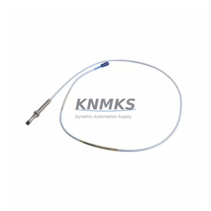
Bently Nevada 330101-00-11-10-02-05 Migration-Ready Proximity Transducer for Legacy Control Systems
The Bently Nevada 330101-00-11-10-02-05 is an 8mm eddy-current proximity transducer engineered for the 3300 XL Series condition monitoring platform. As original equipment reaches end-of-life and OEM support windows close, this unit serves as a verified, migration-ready replacement for facilities managing aging rotating machinery protection systems. Whether you are executing a planned retrofit of a turbine monitoring cabinet, replacing a failed transducer on a compressor train, or extending the operational life of a legacy 3300 XL rack, the 330101-00-11-10-02-05 delivers the signal integrity and dimensional compatibility required for a low-risk, minimum-downtime swap.
This transducer operates within the standard Bently Nevada voltage output range and is designed to interface directly with the 3300 XL proximitor/seismic monitor without requiring signal recalibration or driver replacement in most installations. The 8mm probe tip, 5-meter extension cable configuration, and standard TNC connector ensure that existing conduit routing, terminal block wiring, and rack-mounted monitor inputs can be reused without modification, significantly reducing the scope of work during a planned outage.
Migration Compatibility Table
| Parameter | 330101-00-11-10-02-05 (This Unit) | Retrofit Notes |
|---|---|---|
| Probe Diameter | 8mm | Direct fit for existing 8mm probe holders; no bushing required |
| Cable Length | 5m (extension cable included) | Verify conduit length before installation; extension cable is field-replaceable |
| Connector Type | TNC (standard) | Compatible with 3300 XL proximitor input; no adapter needed |
| Output Sensitivity | 200 mV/mil (7.87 V/mm) | Matches 3300 XL monitor calibration; confirm gap voltage at commissioning |
| Supply Voltage | -24 VDC (nominal) | Verify power supply capacity in existing rack; 3300 XL PSU typically supports direct replacement |
| Target Material Compatibility | AISI 4140 steel (standard) | Confirm shaft material; non-standard alloys may require gap recalibration |
| Installation Space | Standard 8mm probe holder | No mechanical modification required for like-for-like replacement |
| Communication / Monitor Interface | Analog voltage output to 3300 XL monitor | Compatible with 3300 XL/05 and 3300 XL/16 monitor cards |
| Replacement Recommendation | Direct drop-in for 330101 series | Cross-reference against 330180 (reverse-mount) if probe orientation differs |
| Commissioning Focus | Gap voltage, OK LED status, vibration baseline | Set gap to -10.0 VDC ± 0.5 VDC; verify OK relay output before returning to service |
| Support terms | 12 Months | Covers manufacturing defects; includes pre-shipment functional test report |
Retrofit Planning for Existing Automation Systems
Successful integration of the 330101-00-11-10-02-05 into an existing condition monitoring architecture requires a structured pre-outage assessment. Begin by auditing the 3300 XL rack configuration: identify the monitor card slot assignments, confirm that the 3300 XL/05 or 3300 XL/16 monitor cards are present, and document the current gap voltage readings for each installed transducer. This baseline data is essential for post-installation comparison and for validating that the replacement unit is performing within specification.
Terminal block wiring should be mapped before the outage window opens. The 330101-00-11-10-02-05 uses a standard three-conductor cable (shield, signal, and power return), and the existing terminal assignments in the junction box or marshalling cabinet can typically be reused without rewiring. If the installation includes a 3300 XL junction box (such as the 330130 series), verify that the internal wiring diagram matches the replacement transducer’s pinout before energizing the circuit.
For facilities running multiple measurement points on a single compressor or turbine train, it is common to find a mix of radial vibration transducers, axial position probes, and keyphasor transducers all sharing the same 3300 XL rack. When replacing the 330101-00-11-10-02-05 on a radial vibration channel, take the opportunity to inspect adjacent axial position probes (such as the 330103 series) and keyphasor transducers for wear or cable degradation. Replacing worn components during the same outage window reduces future unplanned downtime.
Power supply capacity is a critical checkpoint. The 3300 XL rack power supply module must be verified to support the combined load of all installed transducers and monitor cards. If the rack has been expanded with additional I/O modules or communication interface cards — for example, a 3300 XL/16 monitor card added to support additional measurement points — recalculate the total current draw and confirm the power supply module rating is not exceeded. An undersized power supply is a common root cause of intermittent OK relay faults after a transducer replacement.
If the facility is also migrating from a legacy DCS or PLC platform to a modern control system, the analog vibration signals from the 3300 XL monitors may need to be re-terminated at new I/O marshalling panels. In this scenario, signal isolators or barriers may be required to maintain loop integrity and protect the new control system inputs from ground loops introduced during the transition. Coordinate the transducer replacement with the broader I/O migration plan to avoid creating signal integrity issues that are difficult to diagnose after the outage.
For sites using a Bently Nevada System 1 software platform for online condition monitoring, confirm that the channel configuration in System 1 reflects the replacement transducer’s sensitivity and gap voltage parameters. Incorrect software configuration is a frequent cause of false alarms or missed alerts in the first weeks after a transducer replacement. Update the channel database before returning the machine to service.
Downtime Control During System Migration
Minimizing downtime during a transducer replacement on a critical rotating machine requires preparation that begins well before the outage window. The 330101-00-11-10-02-05 is supplied with a pre-shipment functional test report confirming output sensitivity, insulation resistance, and OK relay behavior, which eliminates the need for incoming inspection testing and allows the unit to be staged for installation immediately upon receipt.
To protect the original program logic and monitor configuration during the replacement, document the current System 1 channel parameters, alert and danger setpoints, and OK relay wiring before disconnecting the existing transducer. This documentation serves as the restoration baseline if the replacement unit requires any parameter adjustment during commissioning. For facilities using a hardwired relay logic scheme rather than a software-based protection system, photograph the relay panel wiring and confirm the relay output assignments before breaking any connections.
The physical replacement procedure for the 330101-00-11-10-02-05 is straightforward: de-energize the monitor channel, disconnect the extension cable at the junction box, remove the existing probe from the probe holder, install the replacement probe, reconnect the extension cable, and re-energize the channel. The entire procedure can typically be completed within 30 to 60 minutes per measurement point by a technician familiar with the 3300 XL system, making it feasible to replace multiple transducers within a single planned maintenance window without extending the outage duration.
After re-energization, verify the gap voltage at the monitor card front panel or through the System 1 interface before releasing the machine for restart. A gap voltage outside the -10.0 VDC ± 0.5 VDC acceptance range indicates either an incorrect probe-to-shaft gap or a wiring issue that must be resolved before the machine is returned to service. Confirm the OK LED status on the monitor card and verify that no latched alerts or danger conditions are present in the protection system before authorizing restart.
Maintaining field control continuity during the replacement is particularly important for machines that cannot be fully isolated from the process. In these cases, coordinate with the operations team to establish a temporary monitoring arrangement — such as portable vibration monitoring equipment — to maintain visibility of machine condition during the period when the permanent monitoring channel is offline. This approach preserves the safety intent of the condition monitoring system without requiring a full process shutdown.
Retrofit Support FAQ
Q: Is the 330101-00-11-10-02-05 a direct replacement for all 330101 series variants?
A: The 330101-00-11-10-02-05 is a direct replacement for other 330101 series configurations sharing the same probe diameter (8mm), cable length (5m), and TNC connector type. Variants with different cable lengths (e.g., 330101-00-11-10-01-05 with a 1m cable) or different connector types are not interchangeable without verifying the extension cable and junction box compatibility. Always cross-reference the full part number before ordering.
Q: What commissioning steps are required after installation?
A: After installation, set the probe-to-shaft gap to achieve a DC gap voltage of -10.0 VDC ± 0.5 VDC at the monitor card input. Verify the OK LED is illuminated and that no alert or danger conditions are latched in the protection system. Update the System 1 channel configuration if sensitivity or gap parameters differ from the previous unit. Record the as-found and as-left gap voltage readings in the maintenance log.
Q: Does the unit ship with a test report, and what does the support terms cover?
A: Yes. Each 330101-00-11-10-02-05 is supplied with a pre-shipment functional test report confirming output sensitivity, insulation resistance, and OK relay operation. The support terms confirmed by quotation cover manufacturing defects in materials and workmanship from the date of shipment. Support requests are supported by our technical team; contact admin@knmks.com with the order number and a description of the observed fault.
Q: What is the typical lead time, and do you maintain stock?
A: We maintain inventory of the 330101-00-11-10-02-05 to support urgent replacement requirements. Standard orders ship within 3 to 5 business days. For critical spares or large-quantity orders, contact admin@knmks.com or call +86 18359268345 to confirm current stock levels and arrange expedited shipment if required.
© 2026 KNMKS. All rights reserved.
Original Source: https://knmks.com
Contact: admin@knmks.com | +86 18359268345
Product Identification
- Brand / Ecosystem
-
Bently Nevada
Bently Nevada - Model / Series
-
330101-00-11-10-02-05
Bently Nevada 3300 XL / 3301 Series - Product Family
- Sensors
- Availability Status
- Available on request after model and quantity confirmation
- Inquiry Type
- B2B RFQ, replacement inquiry and project spare-part request
- Pre-Quote Check
- Exact SKU, brand, series, quantity, nameplate photos and destination country are checked before quotation
System Path
Where this product fits in the KNMKS automation structure.
Specification & Inquiry Focus
- Sensor range
- Photoelectric, proximity and process sensors
- Common needs
- Output type, distance and connector
- Project support
- Machine detection and replacement inquiry
Buyer Confirmation
Information KNMKS checks before replying.
- Exact model
- 330101-00-11-10-02-05
- Brand / ecosystem
- Bently Nevada
- Product family
- Sensors
- Application note
- Replacement, maintenance, project build or spare-part list
- Useful photos
- Nameplate, installed unit, cabinet layout or connector side
- Delivery details
- Quantity, destination country and target schedule
Document Support
Files and notes can be confirmed during quotation.
- Product photos or nameplate confirmation when available
- Packing and delivery notes before quotation confirmation
- Support scope and delivery terms confirmed per inquiry
- Export document coordination for qualified B2B requests
Inquiry Support
- NPN/PNP, analog and digital output checking
- Connector and cable compatibility review
- Fast inquiry support for maintenance teams
What to Send Us
- Brand and exact model number: Bently Nevada 330101-00-11-10-02-05
- Quantity and required delivery time
- Application, replacement requirement or nameplate photo
- Destination country and shipping preference
RFQ Preparation
This is a product inquiry page built for RFQ communication.
Fast Model Check
Send this model to KNMKS for confirmation.
Include quantity, destination country and photos if this is a maintenance replacement. The inquiry will be saved with a reference number after submission.
Brand & Compatibility Note
KNMKS displays automation product information for well-known industrial brand ecosystems and compatible replacement references. Brand names are used for product identification and compatibility reference only; final availability and commercial terms are confirmed per quotation.
 Manufacturing
 Machine Tools
 Packaging
 Energy & Power



 PLCs & Controllers
 HMI & Displays
 Servo Systems
 Variable Frequency Drives