
Overview
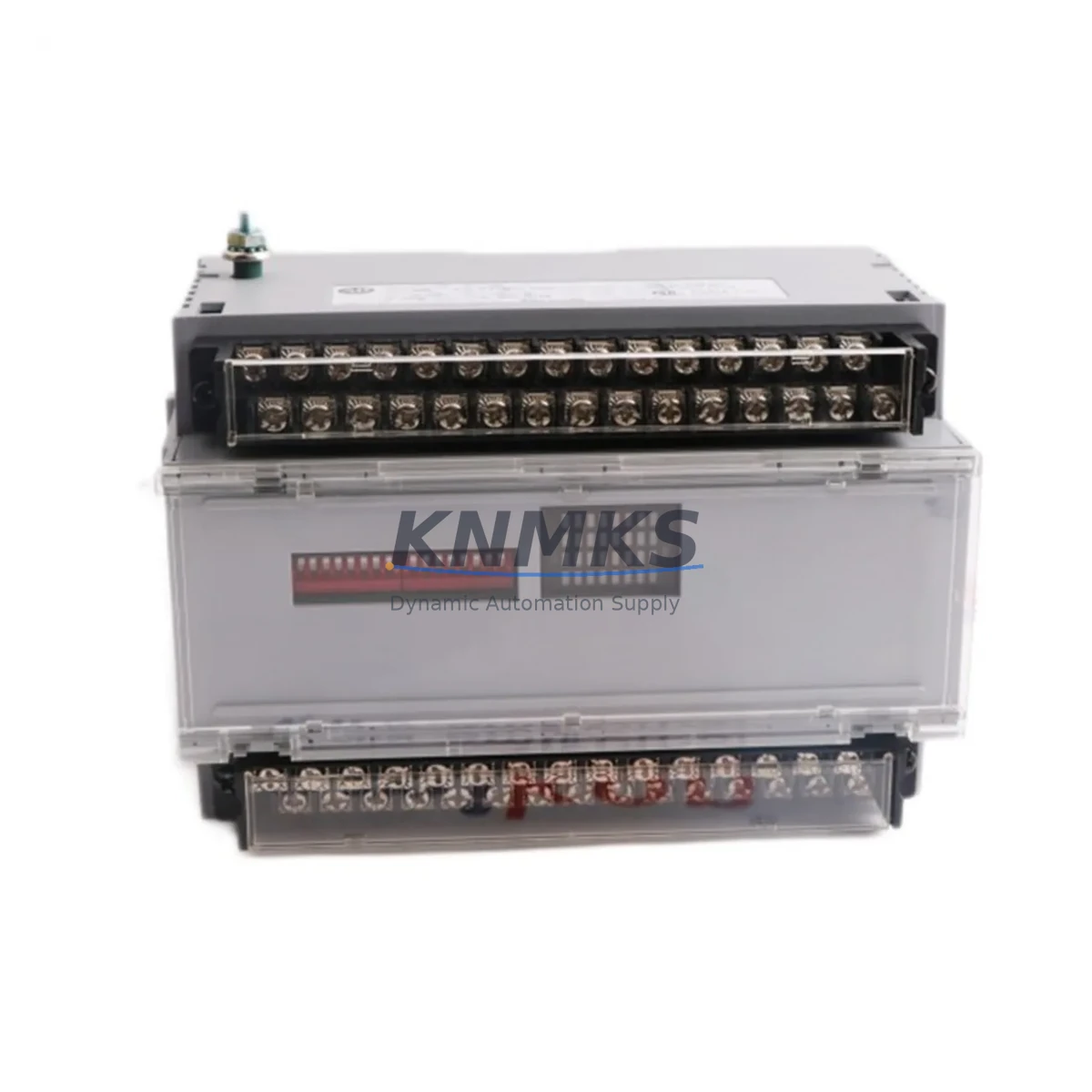
Allen-Bradley 1791-24B8 Migration-Ready Block I/O for Legacy Control Systems
The Allen-Bradley 1791-24B8 is a 24VDC discrete Block I/O module featuring 8 digital inputs and 8 digital outputs, designed for integration into legacy SLC 500 and PLC-5 control architectures. As original 1791 Series hardware reaches end-of-life and spare parts become increasingly scarce, the 1791-24B8 remains one of the most sought-after drop-in replacements for aging distributed I/O nodes across manufacturing, material handling, and process control environments.
For engineers managing brownfield automation systems, sourcing a verified 1791-24B8 is often the fastest path to restoring production without triggering a full control system redesign. This module slots directly into existing 1791 Series block I/O networks, preserving original ladder logic, HMI screen mappings, and field wiring terminations — dramatically reducing retrofit risk and unplanned downtime.
Before installation, engineers should confirm the following: supply voltage at the block (24VDC nominal, verify against existing power supply capacity — typically a 1606-XLP or equivalent Allen-Bradley power supply feeding the I/O network); terminal block wiring compatibility (the 1791-24B8 uses a removable terminal block, allowing field wiring to transfer directly from the failed unit without rewiring); backplane or network drop address settings (verify rotary switch or DIP switch address assignments match the original node address in the PLC program); and communication link integrity on the 1771 remote I/O or DH-485 network segment serving this drop.
Program compatibility is a critical checkpoint. If the host controller is a PLC-5 or SLC 5/04, the I/O map for the 1791-24B8 must align with the original slot addressing. Any mismatch between the configured I/O size in the processor file and the physical module will generate a fault. Verify the I/O configuration file in RSLogix 5 or RSLogix 500 before powering the replacement module. If the system uses a 1747-SN Scanner or 1771-ASB adapter, confirm the rack/group/slot assignments are unchanged.
HMI screen integrity should also be validated post-swap. Systems running PanelView 550, PanelView 900, or FactoryTalk View ME terminals that reference discrete I/O tags mapped to this block should be tested for correct bit-level display and control after the module is energized. Tag database exports from the original project file serve as the fastest reference for cross-checking signal assignments.
Physical installation space is straightforward — the 1791-24B8 mounts directly to standard DIN rail or panel surface using the existing footprint. No bracket modifications are required for standard 1791 Series installations. Confirm conduit entry clearance and cable bend radius before final mounting, particularly in compact control cabinets where space is constrained.
Firmware versioning is not a concern for this discrete I/O block, as the 1791-24B8 does not carry field-upgradeable firmware. However, if the host scanner or adapter module has been updated since original commissioning, verify that the scanner’s I/O block compatibility list still includes the 1791-24B8 device type.
Each unit supplied by KNMKS undergoes pre-shipment functional testing covering input signal detection across all 8 input channels, output switching verification across all 8 output channels, terminal block seating integrity, and LED indicator response. A support terms confirmed by quotation cover all hardware defects from date of shipment.
Migration Compatibility Table
| Parameter | 1791-24B8 Specification | Retrofit Notes |
|---|---|---|
| Input Voltage | 24VDC | Verify existing power supply output; 1606-XLP series recommended |
| Digital Inputs | 8 x 24VDC Sink/Source | Field wiring transfers directly via removable terminal block |
| Digital Outputs | 8 x 24VDC Source | Confirm load current per output channel against existing actuator specs |
| Communication | 1771 Remote I/O / DH-485 | Node address must match original PLC program I/O map |
| Mounting | DIN Rail / Panel Mount | Direct drop-in; no bracket modification required |
| Host Controller Compatibility | PLC-5, SLC 5/04, SLC 5/05 | Verify I/O configuration file in RSLogix 5 / RSLogix 500 |
| Scanner / Adapter | 1747-SN, 1771-ASB | Confirm rack/group/slot assignments unchanged |
| Firmware | Not field-upgradeable | No firmware action required on replacement |
| Pre-Shipment Testing | Full I/O functional test | All 8 inputs and 8 outputs verified before dispatch |
| Support terms | 12 Months | Covers all hardware defects from date of shipment |
Retrofit Planning for Existing Automation Systems
A successful 1791-24B8 retrofit begins well before the replacement module arrives on site. Start by pulling the existing I/O configuration from the PLC program — in RSLogix 500, navigate to the I/O Configuration tree and document the chassis slot, module type, and input/output sizes assigned to the 1791 block node. This record becomes your commissioning checklist.
Power distribution is the first physical checkpoint. The 1791-24B8 draws its 24VDC supply from the field power bus, not the backplane. If the existing Allen-Bradley 1606-XLP power supply is already running near capacity — common in dense I/O cabinets where additional devices have been added over the years — verify available headroom before energizing the replacement. A clamp meter reading on the 24VDC bus during normal operation gives a reliable baseline.
Terminal block transfer is one of the key time-savers in a 1791-24B8 swap. The removable terminal block design means field wiring — sensors, proximity switches, solenoids, and pilot devices — can be disconnected as a single assembly from the failed module and reconnected to the replacement without individual wire removal. Label the terminal block before removal as a precaution, and photograph the wiring layout for reference during reassembly.
Communication link continuity must be maintained throughout the swap. On a 1771 Remote I/O network, the 1791-24B8 node sits on a daisy-chained coaxial or twisted-pair segment. Removing the module briefly interrupts the node, which the PLC scanner will flag as a communication fault. Plan the swap during a scheduled maintenance window, or coordinate with the control room to place the affected I/O group in fault-tolerant mode if the controller supports it.
For systems where the 1791-24B8 works alongside a 1771-OBD output module, a 1771-IB16 input module, or a 1747-L553 SLC 5/05 processor, the retrofit scope may expand to include verifying that adjacent modules in the same rack or I/O drop are also within their service life. A single-module failure in an aging 1791 Series installation is often a leading indicator of broader hardware fatigue across the same control cabinet.
If the retrofit is part of a broader migration toward a ControlLogix or CompactLogix platform, the 1791-24B8 can serve as a bridge solution — maintaining the existing field wiring and I/O network while the new controller infrastructure is staged and tested in parallel. This phased approach keeps the production line running during the transition and allows program conversion and HMI re-mapping to proceed without forcing a hard cutover.
Signal isolation requirements should also be reviewed during planning. If the 1791-24B8 interfaces with third-party sensors operating at different voltage levels or with high common-mode noise environments, a signal isolator or barrier module may be required between the field device and the block I/O input. This is particularly relevant in retrofit scenarios where the original installation predates current grounding and shielding standards.
Downtime Control During System Migration
Minimizing downtime during a 1791-24B8 replacement requires a structured approach that protects the original program logic, maintains field control continuity, and eliminates avoidable commissioning delays.
The most effective downtime reduction strategy is pre-staging. Before the maintenance window opens, have the replacement 1791-24B8 on the bench with its node address pre-configured to match the failed unit. Verify the address setting against the PLC program documentation — do not rely on visual inspection of the failed module’s switch settings if the module has been in service for many years, as switch positions can shift or corrode.
Back up the PLC program before any hardware change. In RSLogix 500, perform a full upload from the processor and save the project file with a date-stamped filename. This backup is your recovery point if the replacement module triggers an unexpected I/O fault or if the processor enters a faulted state during power-up. Store the backup on a local drive and a network share — not only on the programming laptop that will be present on the factory floor.
During the physical swap, keep the maintenance window focused. The 1791-24B8 terminal block transfer, module seating, and communication link reconnection should take under 15 minutes for a prepared technician. The majority of downtime in block I/O replacements comes from undocumented wiring, missing address records, or the need to locate a programming cable — all of which are eliminated by pre-staging.
After power-up, monitor the PLC scanner status bits for the affected I/O drop. In RSLogix 500, the I/O status file will show the communication state of each configured node. A healthy 1791-24B8 replacement will clear the communication fault within one scan cycle. If the fault persists, the most common causes are an incorrect node address, a loose communication cable termination, or a missing end-of-line terminator resistor on the Remote I/O segment.
Final commissioning should include a forced I/O test — momentarily forcing each input bit and verifying the corresponding field device response, then forcing each output bit and confirming actuator operation. This step confirms not only that the replacement module is functioning, but that the terminal block transfer was completed correctly and no wiring transpositions occurred during the swap.
Retrofit Support FAQ
Q: Is the 1791-24B8 a direct replacement for the original Allen-Bradley 1791-24B8 without program changes?
A: Yes. The 1791-24B8 is a form-fit-function replacement for the original module. No changes to the PLC program, I/O configuration file, or HMI tag database are required, provided the node address is set correctly and the communication link is intact.
Q: What pre-shipment testing does KNMKS perform on the 1791-24B8?
A: Each unit undergoes full functional testing covering all 8 input channels and all 8 output channels, terminal block seating verification, and LED indicator response. Test records are available upon request. All units carry a support terms confirmed by quotation from date of shipment.
Q: How do I confirm the correct node address setting before installation?
A: Open the I/O Configuration in RSLogix 500 or RSLogix 5 and locate the 1791 block node entry. The rack and group assignment in the software corresponds to the rotary or DIP switch address on the physical module. Match the replacement module’s address switches to this value before installation.
Q: What is the typical lead time and stock availability for the 1791-24B8?
A: KNMKS maintains inventory of the 1791-24B8 to support urgent replacement requirements. Standard orders ship within 1–3 business days. For large-quantity or project-based procurement, contact admin@knmks.com for availability confirmation and lead time.
© 2026 KNMKS. All rights reserved.
Original Source: https://knmks.com
Contact: admin@knmks.com | +86 18359268345
Product Identification
- Brand / Ecosystem
-
Allen-Bradley
Allen-Bradley - Model / Series
-
1791-24B8
Legacy Series - Product Family
- PLCs & Controllers
- Availability Status
- Available on request after model and quantity confirmation
- Inquiry Type
- B2B RFQ, replacement inquiry and project spare-part request
- Pre-Quote Check
- Exact SKU, brand, series, quantity, nameplate photos and destination country are checked before quotation
System Path
Where this product fits in the KNMKS automation structure.
Specification & Inquiry Focus
- Control platform
- PLC, PAC and modular controllers
- Common needs
- CPU, rack, power and I/O expansion
- Project support
- Replacement, cabinet build and maintenance
Buyer Confirmation
Information KNMKS checks before replying.
- Exact model
- 1791-24B8
- Brand / ecosystem
- Allen-Bradley
- Product family
- PLCs & Controllers
- Application note
- Replacement, maintenance, project build or spare-part list
- Useful photos
- Nameplate, installed unit, cabinet layout or connector side
- Delivery details
- Quantity, destination country and target schedule
Document Support
Files and notes can be confirmed during quotation.
- Product photos or nameplate confirmation when available
- Packing and delivery notes before quotation confirmation
- Support scope and delivery terms confirmed per inquiry
- Export document coordination for qualified B2B requests
Inquiry Support
- Model cross-checking before quotation
- CPU, power, rack and expansion module matching
- Support for replacement and project inquiry
What to Send Us
- Brand and exact model number: Allen-Bradley 1791-24B8
- Quantity and required delivery time
- Application, replacement requirement or nameplate photo
- Destination country and shipping preference
RFQ Preparation
This is a product inquiry page built for RFQ communication.
Fast Model Check
Send this model to KNMKS for confirmation.
Include quantity, destination country and photos if this is a maintenance replacement. The inquiry will be saved with a reference number after submission.
Brand & Compatibility Note
KNMKS displays automation product information for well-known industrial brand ecosystems and compatible replacement references. Brand names are used for product identification and compatibility reference only; final availability and commercial terms are confirmed per quotation.
 Manufacturing
 Machine Tools
 Packaging
 Energy & Power
 HMI & Displays
 Servo Systems
 Variable Frequency Drives
 Sensors