
Overview
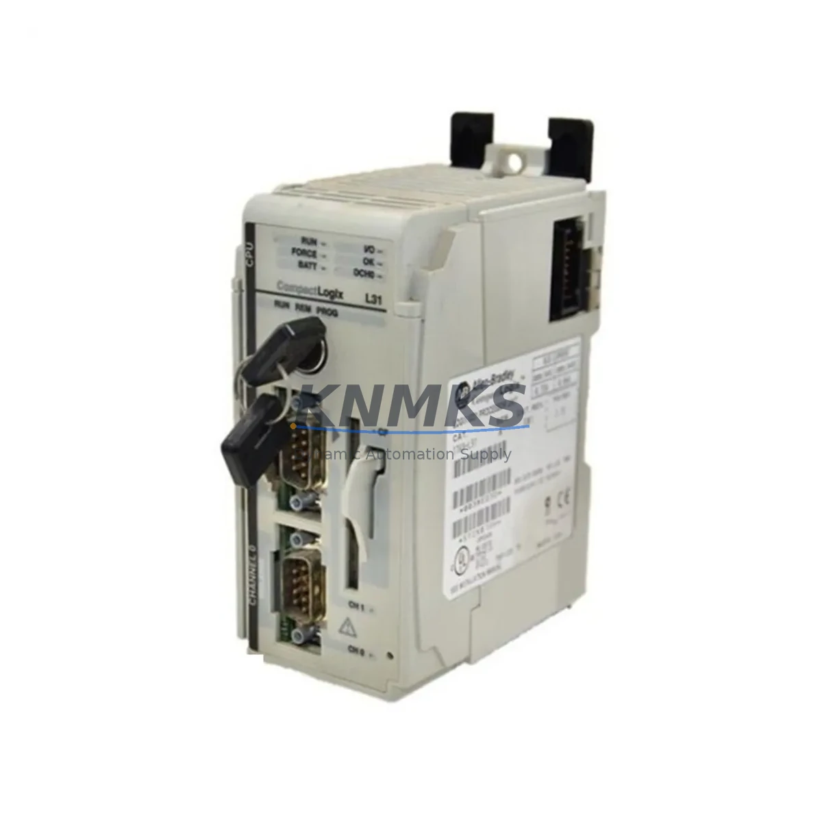
Allen-Bradley 1769-L31 Migration-Ready PLC for Legacy Control Systems
The Allen-Bradley 1769-L31 is a CompactLogix L3x series programmable logic controller designed to serve as a direct migration path for aging SLC 500, MicroLogix, and PLC-5 control platforms. As legacy systems approach end-of-life and spare parts become increasingly scarce, the 1769-L31 provides a proven, field-validated upgrade route that preserves existing I/O infrastructure, minimizes panel rework, and reduces total migration cost. With native EtherNet/IP support, a compact 1769 backplane footprint, and full Studio 5000 / RSLogix 5000 programming compatibility, this processor is the preferred choice for retrofit engineers managing brownfield automation upgrades across discrete manufacturing, process control, and material handling applications.
When planning a migration from a legacy SLC 5/04 or SLC 5/05 system, engineers must verify several critical parameters before commissioning the 1769-L31. Power supply capacity is the first checkpoint: the 1769-PA2 or 1769-PB2 power supply must be sized to support the full local I/O bank, including any 1769-IQ16, 1769-OB16, or 1769-IF4 analog modules already installed in the existing rack. Terminal wiring from the legacy system can typically be reused if the I/O module form factor is preserved, but field wiring polarity, common references, and shield grounding must be re-verified against the new module specifications.
Backplane interface compatibility is a key advantage of the 1769 platform: the 1769-L31 supports up to 16 local I/O modules across a single local bank, and expansion banks can be connected using 1769-CRR1 or 1769-CRL3 right-end caps and cables. Module addressing in the new program must be mapped carefully — RSLogix 5000 uses tag-based addressing rather than the file-based addressing of RSLogix 500, which means all SLC ladder logic must be converted or re-authored. Rockwell Automation’s Migration Assistant tool can accelerate this process, but manual review of timer, counter, and PID instruction blocks is always recommended before live commissioning.
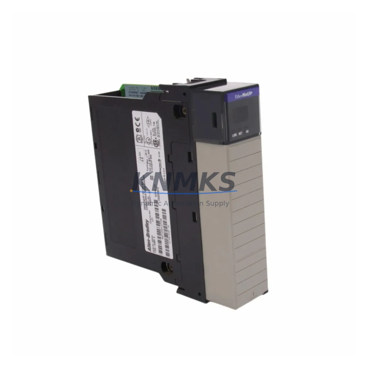
HMI screen migration is another area requiring attention. If the existing system uses a PanelView 300 or PanelView 550 terminal communicating over DH-485 or DH+, the upgrade path typically involves replacing the HMI with a PanelView Plus 7 or PanelView Plus 6 unit and re-authoring screens in FactoryTalk View Studio. The 1769-L31 communicates natively over EtherNet/IP, so a 1761-NET-ENI or 1747-AENTR bridge adapter is not required — the Ethernet port on the processor connects directly to the plant network switch, simplifying the communication architecture and eliminating legacy protocol conversion hardware.
For systems that previously relied on DeviceNet or ControlNet field bus networks, a 1769-SDN DeviceNet scanner module or a 1769-ACN15 ControlNet adapter can be added to the local bank to maintain compatibility with existing field devices during a phased migration. This approach allows the 1769-L31 to take over supervisory control while legacy field devices — including drives, sensors, and remote I/O drops — remain on their original network until a full cutover is planned. Firmware version compatibility between the 1769-L31 processor and any connected 1769 I/O modules should be confirmed using the Rockwell Automation Product Compatibility and Download Center (PCDC) prior to installation.
Installation space is a practical constraint in many retrofit projects. The 1769-L31 occupies a standard DIN rail or panel-mount footprint consistent with other CompactLogix L3x processors, and its overall depth is compatible with most standard 300mm deep control enclosures. If the existing cabinet houses a bulkier SLC 500 rack assembly, the space freed by removing the legacy rack can accommodate the new CompactLogix bank plus a 1769-ECR right-end cap, a 24VDC power supply, and a managed Ethernet switch — all within the original enclosure without sheet metal modification.
All 1769-L31 units supplied by KNMKS are sourced from authorized distribution channels, individually tested for firmware integrity and communication function prior to shipment, and covered by a 12-month replacement support terms. In-stock inventory is maintained to support urgent breakdown replacements and planned shutdown windows. Lead time for standard orders is typically 1–3 business days, with expedited same-day dispatch available for critical production line recoveries.
Migration Compatibility Table
| Parameter | Legacy System (SLC 5/04 / PLC-5) | 1769-L31 CompactLogix | Migration Note |
|---|---|---|---|
| Backplane Interface | 1746 / 1771 rack | 1769 local bank (up to 16 modules) | New 1769 I/O modules required; field wiring reusable |
| Communication Protocol | DH+, DH-485, ControlNet | EtherNet/IP (native), DeviceNet (via 1769-SDN) | HMI and SCADA must support EtherNet/IP or use bridge |
| Programming Software | RSLogix 500 | Studio 5000 / RSLogix 5000 | Tag-based addressing; logic conversion required |
| Power Supply | 1746-P4 / 1771-P4S | 1769-PA2 (120/240VAC) or 1769-PB2 (24VDC) | Verify total I/O current draw before sizing |
| I/O Addressing | File-based (N7, O0, I1) | Tag-based (user-defined) | Full re-mapping required; use Migration Assistant |
| Installation Footprint | Rack-mounted (fixed slot count) | DIN rail / panel mount, modular expansion | Typically fits existing 300mm deep enclosure |
| Firmware Compatibility | N/A (legacy) | Verify via Rockwell PCDC | Match firmware to I/O module catalog revisions |
| Support terms | — | 12-Month Replacement Support terms (KNMKS) | Covers hardware defects and communication faults |
Retrofit Planning for Existing Automation Systems
A successful 1769-L31 retrofit begins with a complete audit of the existing control cabinet. Engineers should document every I/O module slot, its wiring termination, signal type, and current draw before ordering replacement hardware. In most SLC 500 to CompactLogix migrations, the 1769-IQ16 digital input module and 1769-OB16 digital output module serve as direct functional replacements for their 1746-series counterparts, preserving field wiring termination points and reducing rewiring labor. For analog loops, the 1769-IF4 four-channel analog input module handles 4–20mA and 0–10V signals compatible with most legacy transmitter configurations.
Power distribution within the new panel should be re-evaluated. The 1769-PA2 power supply supports up to 2A at 5VDC backplane power, which is sufficient for most 8–12 module local banks. If the retrofit includes communication-intensive modules such as the 1769-SDN DeviceNet scanner or the 1769-L31’s onboard Ethernet port driving multiple I/O adapter nodes, a power budget calculation is mandatory. A 24VDC field power rail, typically sourced from a dedicated SITOP or Phoenix Contact PSU, should be isolated from the backplane supply to prevent noise coupling from inductive field loads.
For systems with existing remote I/O drops connected via RIO cable, a phased migration strategy is recommended: retain the remote racks temporarily using a 1747-ASB adapter while the 1769-L31 takes over local control, then migrate remote drops to EtherNet/IP-based 1734 POINT I/O or 1769 expansion banks during a subsequent planned shutdown. This approach limits the scope of each outage and allows production to resume between migration phases. Programming cables such as the 1784-U2DHP USB-to-DH+ adapter may be needed during the transition period to maintain access to any remaining legacy processors still online.
Downtime Control During System Migration
Minimizing unplanned downtime is the primary operational constraint in any brownfield PLC migration. For the 1769-L31 retrofit, the recommended approach is a parallel commissioning strategy: the new CompactLogix system is fully assembled, programmed, and bench-tested offline before the legacy SLC or PLC-5 is taken out of service. The replacement program should be validated in simulation mode using Studio 5000 Logix Designer’s offline emulation, with all tag mappings, PID tuning parameters, and safety interlock logic verified against the original RSLogix 500 program documentation.
During the cutover window, field wiring is transferred terminal by terminal from the legacy I/O rack to the new 1769 modules, with each circuit verified for continuity and correct signal level before the next is connected. The 1769-L31’s onboard non-volatile memory retains the application program through power cycles, eliminating the risk of program loss during the final power-up sequence. Once the new system is energized, a structured I/O force test — cycling each output and verifying each input through the HMI or a laptop running Studio 5000 — confirms correct wiring before returning the line to automatic mode.
Communication link verification is the final step before handover. The EtherNet/IP connection between the 1769-L31 and the plant SCADA or historian should be confirmed using RSLinx Classic or FactoryTalk Linx, with all tag subscriptions validated at the SCADA level. If the existing HMI uses a legacy protocol driver, a temporary 1761-NET-ENI serial-to-Ethernet bridge can maintain HMI connectivity while the new PanelView or SCADA configuration is finalized in parallel, further reducing the risk of extended production interruption.
Retrofit Support FAQ
Q: Is the 1769-L31 a direct drop-in replacement for the SLC 5/04 or SLC 5/05?
A: The 1769-L31 is a functional replacement, not a physical drop-in. The processor and I/O modules use the 1769 backplane rather than the 1746 rack, so new I/O modules are required. However, existing field wiring can typically be reused, and the migration delivers significant improvements in processing speed, memory capacity, and network connectivity over the legacy SLC platform.
Q: What programming software is required, and is my existing RSLogix 500 logic compatible?
A: The 1769-L31 is programmed using Studio 5000 Logix Designer (or RSLogix 5000 for older firmware versions). RSLogix 500 programs cannot be directly imported, but Rockwell’s Migration Assistant utility can convert a significant portion of ladder logic automatically. Timer, counter, PID, and communication instruction blocks should be manually reviewed and re-tested after conversion.
Q: Does KNMKS test units before shipment, and what support terms is provided?
A: Yes. Every 1769-L31 unit is powered on, firmware-verified, and communication-tested before dispatch. All units are covered by a 12-month replacement support terms covering hardware defects and communication failures under normal operating conditions. Expedited replacement is available for critical production line breakdowns.
Q: Can the 1769-L31 communicate with my existing DeviceNet or ControlNet field devices?
A: Yes, with the appropriate network scanner modules. Adding a 1769-SDN DeviceNet scanner to the local bank allows the 1769-L31 to manage existing DeviceNet field devices including drives, sensors, and valve manifolds. For ControlNet, a 1769-ACN15 adapter module provides the required network interface. Both options support a phased migration approach where legacy field devices remain on their original network while the new processor takes over supervisory control.
© 2026 KNMKS. All rights reserved.
Original Source: https://knmks.com
Contact: admin@knmks.com | +86 18359268345
Product Identification
- Brand / Ecosystem
-
Allen-Bradley
Allen-Bradley - Model / Series
-
1769-L31
ControlLogix Series - Product Family
- PLCs & Controllers
- Availability Status
- Available on request after model and quantity confirmation
- Inquiry Type
- B2B RFQ, replacement inquiry and project spare-part request
- Pre-Quote Check
- Exact SKU, brand, series, quantity, nameplate photos and destination country are checked before quotation
System Path
Where this product fits in the KNMKS automation structure.
Specification & Inquiry Focus
- Control platform
- PLC, PAC and modular controllers
- Common needs
- CPU, rack, power and I/O expansion
- Project support
- Replacement, cabinet build and maintenance
Buyer Confirmation
Information KNMKS checks before replying.
- Exact model
- 1769-L31
- Brand / ecosystem
- Allen-Bradley
- Product family
- PLCs & Controllers
- Application note
- Replacement, maintenance, project build or spare-part list
- Useful photos
- Nameplate, installed unit, cabinet layout or connector side
- Delivery details
- Quantity, destination country and target schedule
Document Support
Files and notes can be confirmed during quotation.
- Product photos or nameplate confirmation when available
- Packing and delivery notes before quotation confirmation
- Support scope and delivery terms confirmed per inquiry
- Export document coordination for qualified B2B requests
Inquiry Support
- Model cross-checking before quotation
- CPU, power, rack and expansion module matching
- Support for replacement and project inquiry
What to Send Us
- Brand and exact model number: Allen-Bradley 1769-L31
- Quantity and required delivery time
- Application, replacement requirement or nameplate photo
- Destination country and shipping preference
RFQ Preparation
This is a product inquiry page built for RFQ communication.
Fast Model Check
Send this model to KNMKS for confirmation.
Include quantity, destination country and photos if this is a maintenance replacement. The inquiry will be saved with a reference number after submission.
Brand & Compatibility Note
KNMKS displays automation product information for well-known industrial brand ecosystems and compatible replacement references. Brand names are used for product identification and compatibility reference only; final availability and commercial terms are confirmed per quotation.
 Manufacturing
 Machine Tools
 Packaging
 Energy & Power
 HMI & Displays
 Servo Systems
 Variable Frequency Drives
 Sensors