
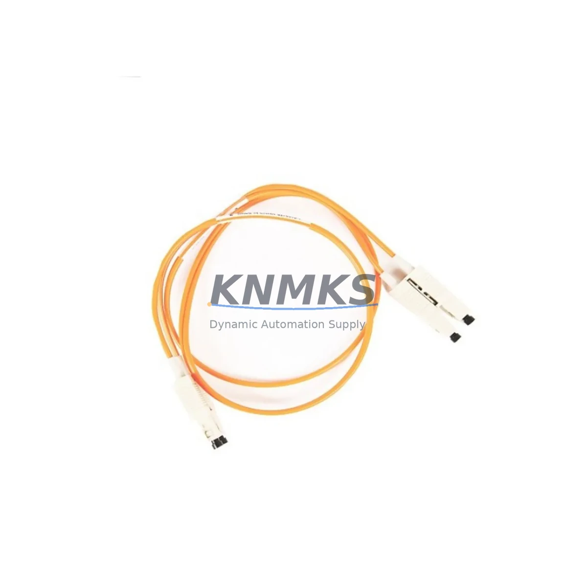
Overview
Allen-Bradley 1757-SRC3 Maintenance-Proven Spare Part for Factory Uptime
The Allen-Bradley 1757-SRC3 is a Redundancy Communication Module (RCM) designed for use within the ControlLogix 1757 Redundancy System. In high-availability manufacturing environments — including automotive assembly, oil & gas processing, water treatment, and continuous chemical production — the 1757-SRC3 serves as the backbone of controller switchover logic, enabling seamless failover between primary and secondary ControlLogix chassis without process interruption. Stocking a verified original 1757-SRC3 spare is a fundamental requirement for any maintenance team operating redundant PLC architectures.
For maintenance engineers, the 1757-SRC3 is a critical line-replaceable unit (LRU). When a redundancy switchover fails to execute cleanly, or when the primary chassis reports a communication fault on the redundancy link, the 1757-SRC3 is the first module to isolate and test. Its fiber-optic redundancy link interface connects the primary and secondary ControlLogix chassis, and any degradation in this link — whether from connector contamination, module aging, or firmware mismatch — can compromise the entire redundancy architecture. Procurement engineers should treat the 1757-SRC3 as a mandatory spare alongside the 1756-RM (Redundancy Module) and the 1756-L6x or 1756-L7x series controllers that anchor the redundant system.
Spare Maintenance Table
| Parameter | Specification |
|---|---|
| Part Number / SKU | 1757-SRC3 |
| Brand | Allen-Bradley (Rockwell Automation) |
| Series | ControlLogix 1757 Redundancy System |
| Module Function | Redundancy Communication Module (RCM) — fiber-optic chassis-to-chassis link |
| Compatible Controllers | 1756-L6x, 1756-L7x ControlLogix Controllers with 1757-SRM Redundancy System |
| Communication Interface | Fiber-optic redundancy link (ST connector) |
| Backplane Compatibility | 1756 ControlLogix Chassis (any slot) |
| Power Consumption | Supplied via 1756 backplane |
| Operating Temperature | 0°C to 60°C (32°F to 140°F) |
| Relative Humidity | 5% to 95% non-condensing |
| Product Condition | Original Spare — tested and verified before shipment |
| Support terms | 12 Months |
| Origin | USA |
| Application | High-availability PLC redundancy, process control, critical infrastructure |
Maintenance Planning for Continuous Operation
When a maintenance team schedules a redundancy system inspection or responds to a switchover fault, the 1757-SRC3 replacement is rarely an isolated task. A thorough site assessment should encompass the entire redundancy architecture to prevent repeat failures and ensure the system returns to full hot-standby status.
Begin with the 1756-RM (Redundancy Module) installed in both the primary and secondary chassis — this module governs the switchover logic and works in direct coordination with the 1757-SRC3 fiber link. Verify firmware versions are synchronized across both modules, as a mismatch is a common root cause of redundancy faults. Next, inspect the 1756-PA75 or 1756-PB75 Power Supply in each chassis; redundancy systems demand stable, uninterrupted backplane power, and a marginal power supply can cause intermittent module resets that mimic communication faults.
Check the 1756-EN2T or 1756-EN3TR EtherNet/IP Communication Modules in both chassis — these carry the real-time I/O and HMI traffic that must continue uninterrupted during a switchover event. Inspect fiber-optic patch cables connecting the two 1757-SRC3 modules for contamination, bend radius violations, or connector wear; ST-type fiber connectors in industrial environments are prone to dust ingress and should be cleaned with appropriate fiber cleaning tools during every scheduled maintenance window.
For the I/O subsystem, audit the 1756-IB16 or 1756-OB16 digital I/O modules and any 1756-IF8 analog input modules for loose terminal connections or drift — a switchover event will expose any latent I/O wiring issues that were masked during normal operation. If the system includes 1756-DNB DeviceNet Bridge Modules or 1756-DHRIO Data Highway Plus/Remote I/O Modules, verify that these legacy communication bridges are also functioning correctly, as they are often overlooked during redundancy-focused maintenance but are critical to overall system availability.
Finally, confirm that the PanelView Plus HMI connected to the system is configured to reconnect automatically after a switchover, and that the SCADA or DCS historian is logging switchover events for trend analysis. Procurement teams should maintain at minimum one spare 1757-SRC3, one spare 1756-RM, and one spare power supply per redundant system pair to meet a target mean-time-to-repair (MTTR) of under four hours.
Site Replacement Workflow
Step 1 — Pre-Replacement Verification: Before removing the 1757-SRC3, confirm the redundant system is in a known state. Use RSLogix 5000 or Studio 5000 Logix Designer to verify that the secondary controller is in SYNCHRONIZED status. If the system is already in a degraded (non-redundant) state due to a module fault, document the fault codes from the controller diagnostics before proceeding.
Step 2 — Controlled Switchover: If the primary chassis is operational, initiate a manual switchover to promote the secondary controller to primary before removing the faulty 1757-SRC3. This ensures process continuity during the replacement and avoids an uncontrolled failover.
Step 3 — Module Removal and Inspection: Power down the affected chassis (now secondary) following Rockwell Automation lockout/tagout procedures. Remove the 1757-SRC3 from its backplane slot. Inspect the backplane connector for bent pins or contamination. Clean the fiber-optic ST connectors on both the module and the patch cable before installing the replacement unit.
Step 4 — Replacement Installation: Insert the new 1757-SRC3 into the same backplane slot. Reconnect the fiber-optic patch cable. Power up the chassis and monitor the module status indicators — the RCM OK LED should illuminate solid green within 30 seconds of backplane power application.
Step 5 — Synchronization Confirmation: From Studio 5000, navigate to the Redundancy tab and confirm the secondary controller transitions from DISQUALIFIED to SYNCHRONIZED. This process may take 1–5 minutes depending on the size of the controller memory image. Do not restore the system to automatic switchover mode until SYNCHRONIZED status is confirmed.
Step 6 — Post-Replacement Test: Perform a manual switchover test to verify the replacement 1757-SRC3 supports a clean failover. Monitor process variables through the HMI during the switchover to confirm zero process disruption. Log the replacement in the site maintenance record with the module serial number, installation date, and technician ID.
Spare Parts Support FAQ
Q1: Is the 1757-SRC3 still available as a new original spare, or is it only available as a refurbished unit?
The 1757-SRC3 is part of the Allen-Bradley 1757 Redundancy System, which Rockwell Automation has placed on a limited-availability lifecycle status. KNMKS supplies original spare units that have been sourced from authorized distribution channels and subjected to pre-shipment functional testing. Each unit is shipped with a support terms confirmed by quotation covering manufacturing defects and functional failures under normal operating conditions. Customers requiring long-term supply agreements for legacy redundancy systems are encouraged to contact our sales team to discuss inventory reservation options.
Q2: How do I verify compatibility between the 1757-SRC3 and my existing ControlLogix redundancy system?
Compatibility is determined by the firmware revision of the 1756-RM Redundancy Module and the ControlLogix controller (1756-L6x or 1756-L7x series) installed in your chassis. The 1757-SRC3 must be paired with a compatible 1756-RM firmware version as specified in Rockwell Automation Publication 1756-UM523. Before ordering, provide your existing 1756-RM catalog number and firmware revision to our technical team, and we will confirm compatibility and advise on any firmware update requirements prior to installation.
Q3: What pre-shipment testing is performed on the 1757-SRC3 before delivery?
Each 1757-SRC3 unit undergoes a multi-point inspection prior to shipment, including visual inspection of the backplane connector and fiber-optic ST ports, power-on self-test verification, and fiber-optic link integrity testing. Units that do not pass all inspection criteria are quarantined and not shipped. A test report is available upon request for customers with quality management system (QMS) documentation requirements.
Q4: What is the recommended spare parts holding strategy for a site operating multiple 1757-SRC3 redundancy pairs?
For sites operating two or more redundant ControlLogix pairs, the recommended minimum spare holding is one 1757-SRC3 per two redundancy pairs, with a maximum replenishment lead time of 72 hours. Sites in remote locations or with extended maintenance intervals should hold one spare per redundancy pair. KNMKS offers blanket purchase order arrangements and consignment stock programs for high-volume industrial customers to ensure spare availability without excessive capital commitment. All units held under consignment agreements are covered by the standard support terms confirmed by quotation from the date of installation, not the date of shipment.
© 2026 KNMKS. All rights reserved.
Original Source: https://knmks.com
Contact: admin@knmks.com | +86 18359268345
Product Identification
- Brand / Ecosystem
-
Allen-Bradley
Allen-Bradley - Model / Series
-
1757-SRC3
ControlLogix Series - Product Family
- PLCs & Controllers
- Availability Status
- Available on request after model and quantity confirmation
- Inquiry Type
- B2B RFQ, replacement inquiry and project spare-part request
- Pre-Quote Check
- Exact SKU, brand, series, quantity, nameplate photos and destination country are checked before quotation
System Path
Where this product fits in the KNMKS automation structure.
Specification & Inquiry Focus
- Control platform
- PLC, PAC and modular controllers
- Common needs
- CPU, rack, power and I/O expansion
- Project support
- Replacement, cabinet build and maintenance
Buyer Confirmation
Information KNMKS checks before replying.
- Exact model
- 1757-SRC3
- Brand / ecosystem
- Allen-Bradley
- Product family
- PLCs & Controllers
- Application note
- Replacement, maintenance, project build or spare-part list
- Useful photos
- Nameplate, installed unit, cabinet layout or connector side
- Delivery details
- Quantity, destination country and target schedule
Document Support
Files and notes can be confirmed during quotation.
- Product photos or nameplate confirmation when available
- Packing and delivery notes before quotation confirmation
- Support scope and delivery terms confirmed per inquiry
- Export document coordination for qualified B2B requests
Inquiry Support
- Model cross-checking before quotation
- CPU, power, rack and expansion module matching
- Support for replacement and project inquiry
What to Send Us
- Brand and exact model number: Allen-Bradley 1757-SRC3
- Quantity and required delivery time
- Application, replacement requirement or nameplate photo
- Destination country and shipping preference
RFQ Preparation
This is a product inquiry page built for RFQ communication.
Fast Model Check
Send this model to KNMKS for confirmation.
Include quantity, destination country and photos if this is a maintenance replacement. The inquiry will be saved with a reference number after submission.
Brand & Compatibility Note
KNMKS displays automation product information for well-known industrial brand ecosystems and compatible replacement references. Brand names are used for product identification and compatibility reference only; final availability and commercial terms are confirmed per quotation.
 Manufacturing
 Machine Tools
 Packaging
 Energy & Power
 HMI & Displays
 Servo Systems
 Variable Frequency Drives
 Sensors