
Overview
Allen-Bradley 1756-RMC10 Migration-Ready RMC Interface for Legacy Control Systems
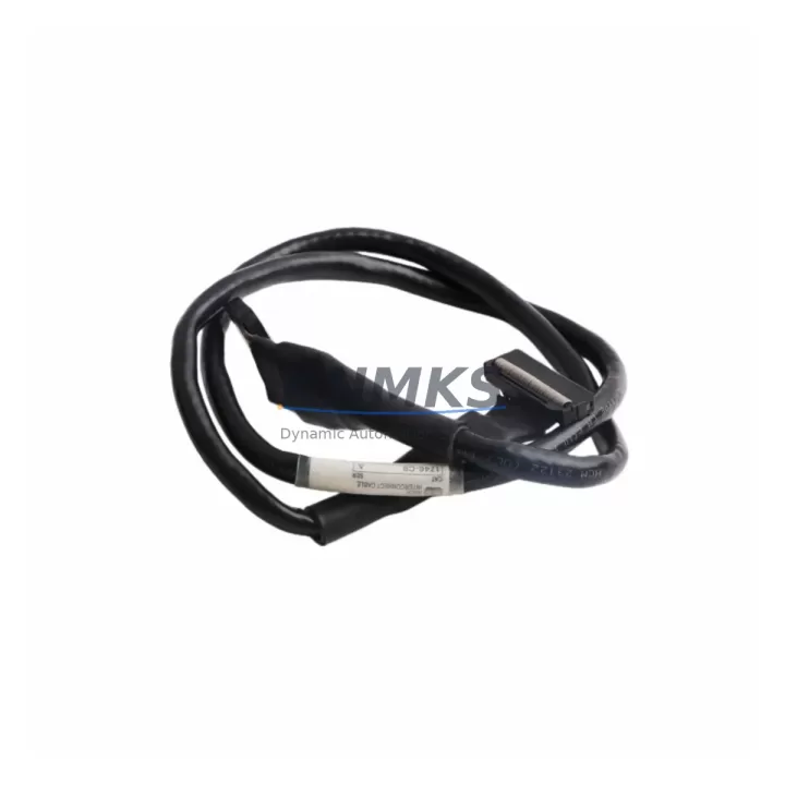
The Allen-Bradley 1756-RMC10 is a critical RMC (Remote Motion Controller) interface cable designed for ControlLogix platform deployments. As legacy automation systems approach end-of-life, the 1756-RMC10 serves as a validated, migration-ready replacement component that enables engineers to extend the operational life of existing control cabinets without requiring a full platform overhaul. Whether you are managing a phased retrofit of a petrochemical process line, upgrading a legacy power generation control system, or restoring a discontinued spare parts inventory for a mining or port operations facility, the 1756-RMC10 provides the physical and electrical interface continuity required to maintain system integrity during transition.
Before deploying the 1756-RMC10 as a replacement in an existing ControlLogix rack, engineers should verify several key parameters. Power capacity within the 1756-A7 or 1756-A13 chassis must be confirmed against the total module load, particularly when the retrofit involves adding new I/O modules or communication adapters alongside the RMC interface. Terminal wiring at the motion controller end must be inspected for compatibility with the existing cable harness, as connector pinout differences between legacy RMC generations can introduce signal integrity issues if not addressed during pre-installation review. Backplane slot addressing must be re-confirmed in RSLogix 5000 or Studio 5000 Logix Designer after physical installation, since slot-based module addressing directly affects the motion axis configuration and program tag mapping.
Program compatibility is a frequent concern during RMC interface replacement. Existing ladder logic routines and motion instruction blocks referencing the original 1756-RMC10 axis parameters should be exported and archived before any hardware swap. If the replacement unit involves a firmware revision change, axis tuning parameters, velocity feedforward gains, and position loop configurations may require re-validation against the original motion profile. HMI screen tag bindings in FactoryTalk View SE or ME should also be audited to ensure that axis status tags and fault codes remain correctly mapped after the interface replacement. Communication link integrity between the ControlLogix controller and the RMC motion controller — typically via the 1756-RMC10 cable — must be verified using RSLinx Classic or Studio 5000 online diagnostics before returning the system to automatic mode.
Migration Compatibility Table
| Parameter | Details |
|---|---|
| Compatible Platform | Allen-Bradley ControlLogix (1756 Series) |
| Compatible Chassis | 1756-A4, 1756-A7, 1756-A10, 1756-A13, 1756-A17 |
| Interface Type | RMC (Remote Motion Controller) Cable Interface |
| Connector Compatibility | Verify pinout against legacy RMC generation before installation |
| Backplane Communication | ControlLogix backplane; slot address must be configured in Studio 5000 |
| Firmware Compatibility | Confirm firmware revision alignment with existing motion controller |
| Installation Space | Standard 1756 chassis slot; no additional mounting hardware required |
| Replacement Recommendation | Direct drop-in for legacy 1756-RMC10; verify axis tag mapping post-swap |
| Commissioning Focus | Axis tuning, HMI tag binding, RSLinx communication verification |
| Support terms | support terms confirmed by quotation | Pre-shipment tested | Global stock available |
Retrofit Planning for Existing Automation Systems
Successful integration of the 1756-RMC10 into a legacy retrofit project requires a structured approach to component selection and sequencing. In a typical ControlLogix-based motion control cabinet undergoing modernization, the 1756-RMC10 interface cable works in conjunction with the 1756-M02AE or 1756-M03SE servo drive interface modules, which manage the physical drive communication layer. Engineers planning a phased upgrade should also account for the 1756-EN2T EtherNet/IP communication module, which is commonly used to bridge legacy DeviceNet or DH+ networks to a modern Ethernet backbone during protocol migration. If the existing system relies on a 1756-DNB DeviceNet bridge module for field device communication, the retrofit plan must include a parallel communication path validation to ensure that I/O data continuity is maintained during the transition period.
For systems where the motion controller interfaces with legacy servo drives via analog command signals, the addition of a 1492-AIFM analog interface module or equivalent signal conditioning terminal block may be required to adapt the wiring harness to the new interface standard. In control cabinets where space is constrained, the physical dimensions of the 1756-RMC10 cable routing must be planned alongside the 1756-PA75 or 1756-PB75 power supply module to avoid interference with existing wiring bundles. Programming cable access for firmware updates — typically via a 1756-USB or 1784-U2DHP USB-to-DH+ adapter — should also be confirmed as part of the pre-retrofit site survey to avoid on-site delays during commissioning.
Downtime Control During System Migration
Minimizing unplanned downtime during an RMC interface replacement requires a disciplined pre-migration checklist and a clearly defined rollback procedure. Before removing the legacy 1756-RMC10, the existing motion program should be fully backed up using Studio 5000 project export, and all axis configuration parameters — including encoder feedback scaling, velocity limits, and torque limits — should be documented in a commissioning record. The replacement unit should be bench-tested against a known-good ControlLogix chassis prior to site installation to confirm that the interface cable establishes correct communication with the motion controller within the expected initialization time.
During the physical swap, the control system should be placed in a safe state with all motion axes inhibited and all field devices confirmed in a de-energized condition. After installation, the 1756-RMC10 should be brought online incrementally: first confirming backplane communication, then verifying axis feedback signals, and finally executing a slow-speed motion test before returning to full production speed. This staged commissioning approach protects the original program logic, maintains field control continuity, and significantly reduces the risk of unplanned process interruptions. All pre-shipment testing records and firmware version documentation supplied with the replacement unit should be retained as part of the site maintenance record to support future audits and support requests.
Retrofit Support FAQ
Q: Is the 1756-RMC10 a direct replacement for the original Allen-Bradley unit?
A: Yes. The 1756-RMC10 supplied by KNMKS is a verified replacement for the original Allen-Bradley 1756-RMC10 RMC interface cable. Each unit undergoes pre-shipment functional testing to confirm connector integrity and signal continuity before dispatch. Engineers should verify firmware revision compatibility with the installed motion controller as part of the standard commissioning procedure.
Q: What wiring checks are required before installation?
A: Prior to installation, confirm that the existing cable harness connector pinout matches the 1756-RMC10 interface specification. Inspect terminal contacts for corrosion or mechanical damage, and verify that the cable routing within the control cabinet does not create excessive bend radius stress on the connector housing. If the legacy installation used a non-standard wiring harness, a custom adapter may be required.
Q: How is compatibility with Studio 5000 and RSLogix 5000 confirmed?
A: After physical installation, bring the module online in Studio 5000 and verify that the axis configuration tags are correctly populated. Run the RSLinx Classic communication diagnostic to confirm that the motion controller is visible on the backplane. Execute a controlled jog test at reduced speed before enabling full production motion profiles. Any axis tuning discrepancies should be resolved before returning the system to automatic operation.
Q: What support terms and stock availability does KNMKS provide?
A: All 1756-RMC10 units supplied by KNMKS carry a support terms confirmed by quotation covering manufacturing defects and functional failures under normal operating conditions. Stock is maintained for immediate dispatch to support urgent replacement requirements across global sites. Contact our technical sales team for lead time confirmation and volume pricing on multi-unit retrofit projects.
© 2026 KNMKS. All rights reserved.
Original Source: https://knmks.com
Contact: admin@knmks.com | +86 18359268345
Product Identification
- Brand / Ecosystem
-
Allen-Bradley
Allen-Bradley - Model / Series
-
1756-RMC10
ControlLogix Series - Product Family
- Relays & Interface
- Availability Status
- Available on request after model and quantity confirmation
- Inquiry Type
- B2B RFQ, replacement inquiry and project spare-part request
- Pre-Quote Check
- Exact SKU, brand, series, quantity, nameplate photos and destination country are checked before quotation
System Path
Where this product fits in the KNMKS automation structure.
Specification & Inquiry Focus
- Interface range
- Relays, isolation and signal modules
- Common needs
- Coil voltage and contact rating
- Project support
- Panel wiring and signal protection
Buyer Confirmation
Information KNMKS checks before replying.
- Exact model
- 1756-RMC10
- Brand / ecosystem
- Allen-Bradley
- Product family
- Relays & Interface
- Application note
- Replacement, maintenance, project build or spare-part list
- Useful photos
- Nameplate, installed unit, cabinet layout or connector side
- Delivery details
- Quantity, destination country and target schedule
Document Support
Files and notes can be confirmed during quotation.
- Product photos or nameplate confirmation when available
- Packing and delivery notes before quotation confirmation
- Support scope and delivery terms confirmed per inquiry
- Export document coordination for qualified B2B requests
Inquiry Support
- Relay base and module matching
- Signal isolation and protection options
- Panel accessory inquiry support
What to Send Us
- Brand and exact model number: Allen-Bradley 1756-RMC10
- Quantity and required delivery time
- Application, replacement requirement or nameplate photo
- Destination country and shipping preference
RFQ Preparation
This is a product inquiry page built for RFQ communication.
Fast Model Check
Send this model to KNMKS for confirmation.
Include quantity, destination country and photos if this is a maintenance replacement. The inquiry will be saved with a reference number after submission.
Brand & Compatibility Note
KNMKS displays automation product information for well-known industrial brand ecosystems and compatible replacement references. Brand names are used for product identification and compatibility reference only; final availability and commercial terms are confirmed per quotation.
 Manufacturing
 Machine Tools
 Packaging
 Energy & Power
 PLCs & Controllers
 HMI & Displays
 Servo Systems
 Variable Frequency Drives