
Overview
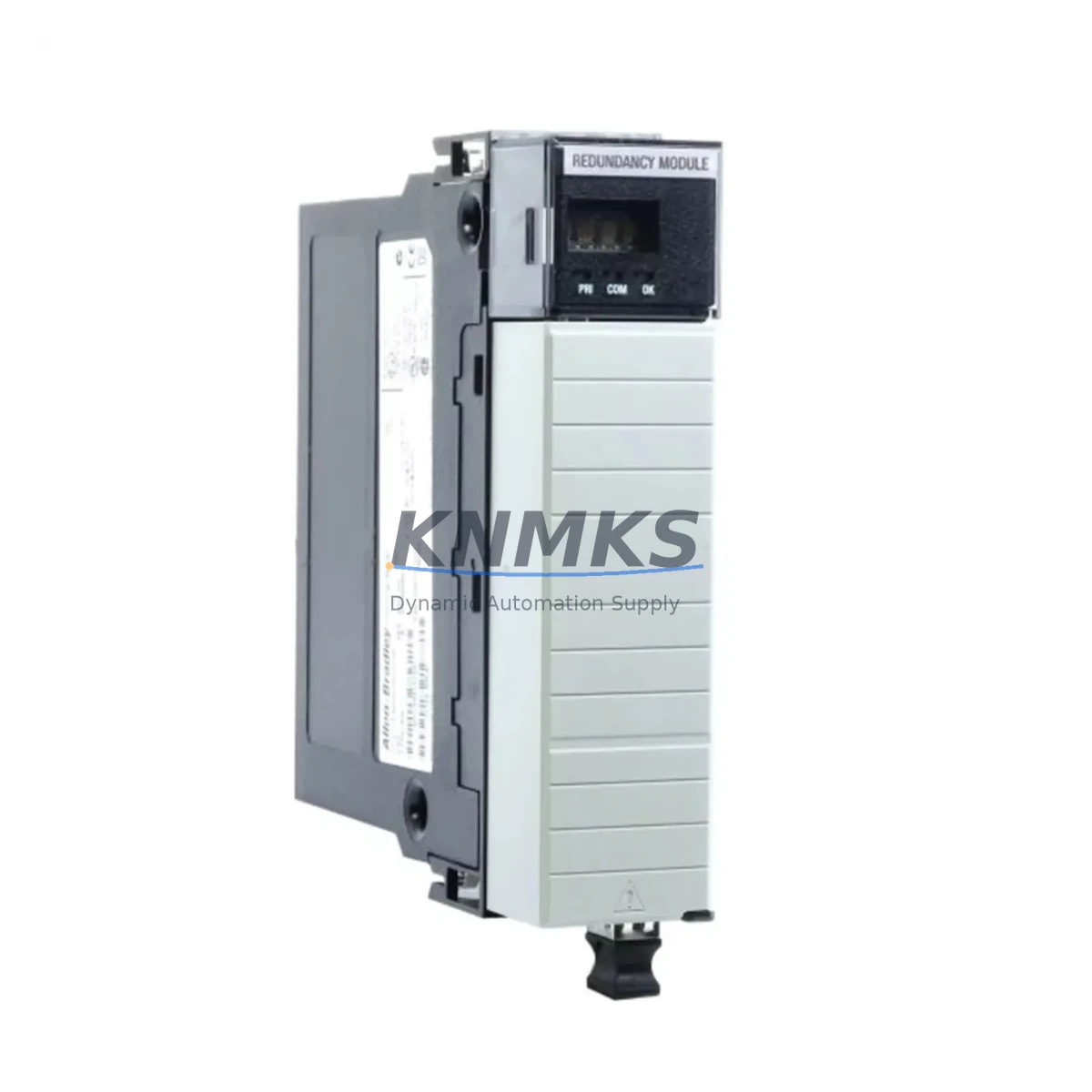
Allen-Bradley 1756-RM/B Maintenance-Proven Spare Part for Factory Uptime
The Allen-Bradley 1756-RM/B is a ControlLogix Redundancy Module designed for mission-critical industrial control systems where unplanned downtime is not an option. As a genuine original spare part, the 1756-RM/B enables hot-standby redundancy between two ControlLogix chassis, ensuring seamless switchover during fault conditions without interrupting process control. For maintenance engineers managing continuous-process plants, automotive assembly lines, or utility infrastructure, keeping a qualified 1756-RM/B in your spare parts inventory is a fundamental risk-mitigation strategy.
At KNMKS, every 1756-RM/B unit is sourced from verified supply channels, functionally tested prior to shipment, and backed by a support terms confirmed by quotation. We understand that procurement engineers require not only the correct part number but also confidence in lead time, traceability, and long-term availability — especially for aging ControlLogix 1756 systems that may no longer be in active production support cycles.
Whether you are responding to an emergency fault, executing a planned annual shutdown, or building a strategic spare parts buffer, the 1756-RM/B from KNMKS is ready for immediate dispatch with full documentation support.
Spare Maintenance Table
| Parameter | Specification |
|---|---|
| Part Number | 1756-RM/B |
| Brand | Allen-Bradley (Rockwell Automation) |
| Series | ControlLogix 1756 |
| Product Type | PLC Redundancy Module |
| Redundancy Mode | Hot-Standby (Primary / Secondary Chassis) |
| Communication Interface | Redundancy Communication Cable (1756-RMC / 1756-RMCT) |
| Backplane Compatibility | ControlLogix 1756 Backplane (1756-A4, 1756-A7, 1756-A10, 1756-A13, 1756-A17) |
| Power Supply Compatibility | 1756-PA72, 1756-PB72, 1756-PA75, 1756-PB75 |
| Operating Temperature | 0°C to 60°C (32°F to 140°F) |
| Relative Humidity | 5% to 95% non-condensing |
| Installation Environment | Industrial control cabinet, DIN rail or chassis slot mount |
| Firmware Compatibility | RSLogix 5000 / Studio 5000 Logix Designer |
| Condition | Original, factory-tested before shipment |
| Support terms | 12 Months |
| Origin | United States |
Maintenance Planning for Continuous Operation
When replacing or inspecting the 1756-RM/B in a live ControlLogix redundancy system, a disciplined maintenance workflow extends well beyond swapping the module itself. Maintenance engineers should treat the redundancy module replacement as a trigger for a broader control cabinet inspection to prevent cascading failures.
Begin by verifying the 1756-RMC or 1756-RMCT redundancy communication cable — the fiber-optic or copper link between the primary and secondary chassis. A degraded cable is a common root cause of redundancy synchronization faults and is frequently overlooked during emergency replacements. Inspect both cable connectors and the cable routing for mechanical damage or excessive bend radius.
Next, audit the ControlLogix power supplies in both chassis. The 1756-PA72 and 1756-PB72 are the most common companions to the 1756-RM/B. Measure output voltage under load and check for capacitor aging indicators such as output ripple or thermal discoloration on the module faceplate. A failing power supply in the secondary chassis can prevent a successful switchover even when the redundancy module itself is healthy.
Inspect the 1756 backplane (chassis) for corrosion on the backplane connector pins, particularly in high-humidity or coastal industrial environments. Backplane connector oxidation causes intermittent communication errors that are difficult to diagnose without physical inspection. If the system has been in service for more than seven years, consider scheduling a chassis replacement during the next planned outage.
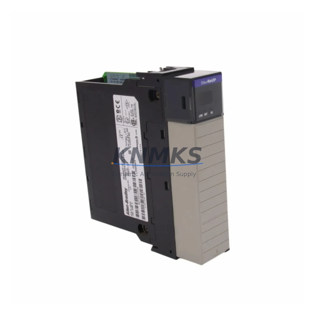
Review the 1756-EN2T or 1756-ENBT EtherNet/IP communication modules in both the primary and secondary chassis. Redundancy switchover depends on network topology consistency between chassis; mismatched firmware versions or IP configuration errors on communication modules are a known source of switchover failures. Confirm that both chassis carry identical module configurations and firmware revisions.
For systems with analog I/O, inspect the 1756-IF16 or 1756-OF8 analog I/O modules for signal drift or calibration deviation. Redundancy switchover can expose latent I/O calibration issues that were masked during normal primary-chassis operation. Include I/O calibration verification in your post-switchover commissioning checklist.
Finally, check the 24VDC field power distribution feeding I/O terminal blocks and relay coils. Loose terminal connections and aging fuse holders in the field power circuit are a disproportionate source of nuisance faults in aging ControlLogix installations. Torque-check all terminal screws and replace any discolored or heat-stressed fuse holders as part of the annual inspection cycle.
Site Replacement Workflow
Step 1 — Pre-Replacement Verification: Confirm the replacement 1756-RM/B firmware revision matches or is compatible with the existing primary chassis controller firmware. Mismatched firmware between the redundancy module and the Logix controller is the leading cause of failed redundancy qualification after module swap. Download the current firmware version from the primary chassis using Studio 5000 before removing the faulty module.
Step 2 — Safe Removal: The 1756-RM/B can be removed and inserted with the chassis powered in most ControlLogix configurations, but always verify the system’s redundancy state in RSLogix 5000 / Studio 5000 before hot-swapping. Initiate a manual switchover to the secondary chassis to ensure the primary chassis is in a non-controlling state before removing the module. This eliminates the risk of a process upset during the replacement.
Step 3 — Module Installation and Cable Connection: Insert the replacement 1756-RM/B into the designated chassis slot. Reconnect the redundancy communication cable (1756-RMC or 1756-RMCT) and verify the cable lock is fully engaged. A partially seated cable connector is a common installation error that prevents redundancy synchronization.
Step 4 — Redundancy Qualification: Use Studio 5000 Logix Designer to initiate the redundancy qualification sequence. Monitor the synchronization status until the secondary chassis achieves a fully qualified standby state. Document the qualification timestamp and firmware versions for your maintenance records.
Step 5 — Post-Replacement Functional Test: Perform a controlled manual switchover to confirm that the newly installed 1756-RM/B supports a clean transition. Verify that all I/O, communication modules, and HMI connections recover correctly after switchover. Return the system to automatic redundancy mode and update your spare parts inventory log.
This workflow is applicable to both emergency fault-response replacements and planned annual maintenance replacements. For aging ControlLogix systems approaching end-of-life support, KNMKS recommends maintaining a minimum of one qualified 1756-RM/B unit per redundant system pair in your on-site spare parts buffer.
Spare Parts Support FAQ
Q1: Is the 1756-RM/B compatible with all ControlLogix 1756 chassis and controller revisions?
The 1756-RM/B is designed for use with ControlLogix 1756 series chassis and is compatible with a wide range of 1756 controllers including the 1756-L61, 1756-L62, 1756-L63, 1756-L64, and 1756-L65 series. Compatibility with specific firmware revisions should be verified against the Rockwell Automation Redundancy System User Manual (Publication 1756-UM523) before installation. KNMKS provides pre-shipment firmware verification upon request to reduce on-site compatibility risk.
Q2: How does KNMKS verify the 1756-RM/B before shipment?
Every 1756-RM/B unit supplied by KNMKS undergoes functional testing prior to dispatch. Testing includes power-on self-test verification, backplane communication check, and visual inspection for physical damage or counterfeit indicators. Units are shipped with a test report and are covered by a support terms confirmed by quotation from the date of shipment. If a unit fails within the confirmed support period, KNMKS provides replacement or documented resolution support.
Q3: What is the recommended spare parts inventory strategy for 1756-RM/B in a multi-system plant?
For plants operating two or more ControlLogix redundancy pairs, the industry-standard recommendation is to maintain one spare 1756-RM/B per two redundant system pairs, with a minimum of one unit on-site at all times. Given that the 1756-RM/B is a critical single point of failure for the redundancy function, procurement engineers should also consider the supplier’s lead time and stock availability when setting reorder points. KNMKS maintains standing inventory of the 1756-RM/B to support emergency same-day dispatch requirements.
Q4: Can the 1756-RM/B replace older redundancy module revisions such as the 1756-RM or 1756-RM/A?
The 1756-RM/B is a revised version of the original 1756-RM and 1756-RM/A. In most ControlLogix redundancy configurations, the /B revision is backward-compatible as a replacement for earlier revisions, provided the system firmware is updated to a compatible version. KNMKS recommends consulting the Rockwell Automation release notes for your specific controller firmware version before substituting module revisions in a live system. Our technical team can assist with compatibility verification prior to purchase.
© 2026 KNMKS. All rights reserved.
Original Source: https://knmks.com
Contact: admin@knmks.com | +86 18359268345
Product Identification
- Brand / Ecosystem
-
Allen-Bradley
Allen-Bradley - Model / Series
-
1756-RM/B
ControlLogix Series - Product Family
- PLCs & Controllers
- Availability Status
- Available on request after model and quantity confirmation
- Inquiry Type
- B2B RFQ, replacement inquiry and project spare-part request
- Pre-Quote Check
- Exact SKU, brand, series, quantity, nameplate photos and destination country are checked before quotation
System Path
Where this product fits in the KNMKS automation structure.
Specification & Inquiry Focus
- Control platform
- PLC, PAC and modular controllers
- Common needs
- CPU, rack, power and I/O expansion
- Project support
- Replacement, cabinet build and maintenance
Buyer Confirmation
Information KNMKS checks before replying.
- Exact model
- 1756-RM/B
- Brand / ecosystem
- Allen-Bradley
- Product family
- PLCs & Controllers
- Application note
- Replacement, maintenance, project build or spare-part list
- Useful photos
- Nameplate, installed unit, cabinet layout or connector side
- Delivery details
- Quantity, destination country and target schedule
Document Support
Files and notes can be confirmed during quotation.
- Product photos or nameplate confirmation when available
- Packing and delivery notes before quotation confirmation
- Support scope and delivery terms confirmed per inquiry
- Export document coordination for qualified B2B requests
Inquiry Support
- Model cross-checking before quotation
- CPU, power, rack and expansion module matching
- Support for replacement and project inquiry
What to Send Us
- Brand and exact model number: Allen-Bradley 1756-RM/B
- Quantity and required delivery time
- Application, replacement requirement or nameplate photo
- Destination country and shipping preference
RFQ Preparation
This is a product inquiry page built for RFQ communication.
Fast Model Check
Send this model to KNMKS for confirmation.
Include quantity, destination country and photos if this is a maintenance replacement. The inquiry will be saved with a reference number after submission.
Brand & Compatibility Note
KNMKS displays automation product information for well-known industrial brand ecosystems and compatible replacement references. Brand names are used for product identification and compatibility reference only; final availability and commercial terms are confirmed per quotation.
 Manufacturing
 Machine Tools
 Packaging
 Energy & Power
 HMI & Displays
 Servo Systems
 Variable Frequency Drives
 Sensors