
Overview
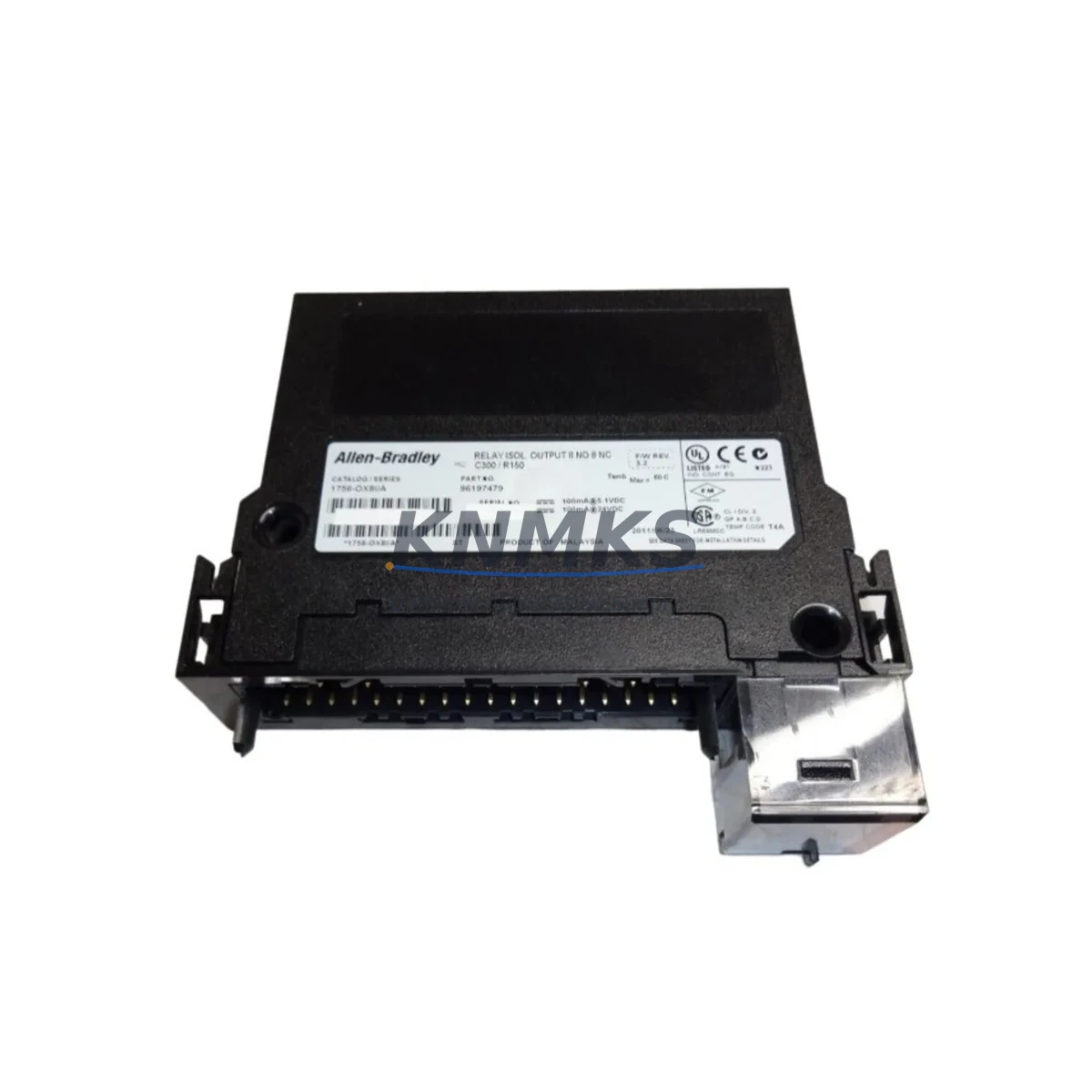
Allen-Bradley 1756-OX8I Spare Part for Factory Uptime
The Allen-Bradley 1756-OX8I is an 8-point isolated relay output module designed for the ControlLogix 1756 Series platform — one of the most widely deployed PLC architectures in discrete manufacturing, process control, and critical infrastructure. As a maintenance-proven spare part, the 1756-OX8I supports rapid field replacement, minimizes unplanned downtime, and ensures your control system remains operational through scheduled and emergency maintenance cycles.
Sourced as an original spare, each 1756-OX8I unit is inspected and tested prior to shipment. With a support terms confirmed by quotation and long-term supply commitment, this module is suitable for both immediate emergency replacement and strategic spare parts inventory programs.
Spare Maintenance Table
| Parameter | Specification |
|---|---|
| SKU / Part Number | 1756-OX8I |
| Brand | Allen-Bradley (Rockwell Automation) |
| Series | ControlLogix 1756 |
| Module Type | Isolated Relay Output |
| Output Points | 8 (individually isolated) |
| Output Voltage Range | 10–265V AC/DC |
| Max Current per Point | 2A (resistive load) |
| Isolation | Channel-to-channel isolated |
| Backplane Current (5V) | 120 mA |
| Backplane Current (24V) | 3 mA |
| Operating Temperature | 0–60°C |
| Compatibility | ControlLogix 1756 chassis, all standard 1756 backplanes |
| Installation | Hot-swap capable (with appropriate chassis support) |
| Maintenance Recommendation | Inspect relay contacts annually; replace at first sign of contact wear or output fault |
| Support terms | 12 Months |
| Condition | Original Spare / Tested Before Shipment |
Maintenance Planning for Continuous Operation
When a 1756-OX8I relay output module is flagged during routine control cabinet inspection or fault diagnostics, experienced maintenance engineers know that replacing the module alone is rarely sufficient for a complete and reliable restoration. A thorough site assessment should accompany every 1756-OX8I swap.
Begin by verifying the integrity of the 1756-PA75 or 1756-PB75 power supply module feeding the ControlLogix chassis. Relay output modules are sensitive to power quality fluctuations, and a degraded power supply can accelerate contact wear or cause intermittent output faults that mimic module failure. While the chassis is open, inspect the 1756-A7 or 1756-A13 backplane for signs of corrosion, loose module retention, or connector damage — backplane issues are a common root cause of misdiagnosed output module faults.
Check all field wiring connected to the 1756-OX8I’s removable terminal block (RTB). Loose or corroded terminals on high-cycle relay outputs are a leading cause of premature contact failure. If the application involves motor starters, solenoid valves, or pilot lights, verify that appropriate surge suppressors or RC snubber circuits are installed across inductive loads — their absence significantly shortens relay contact life.
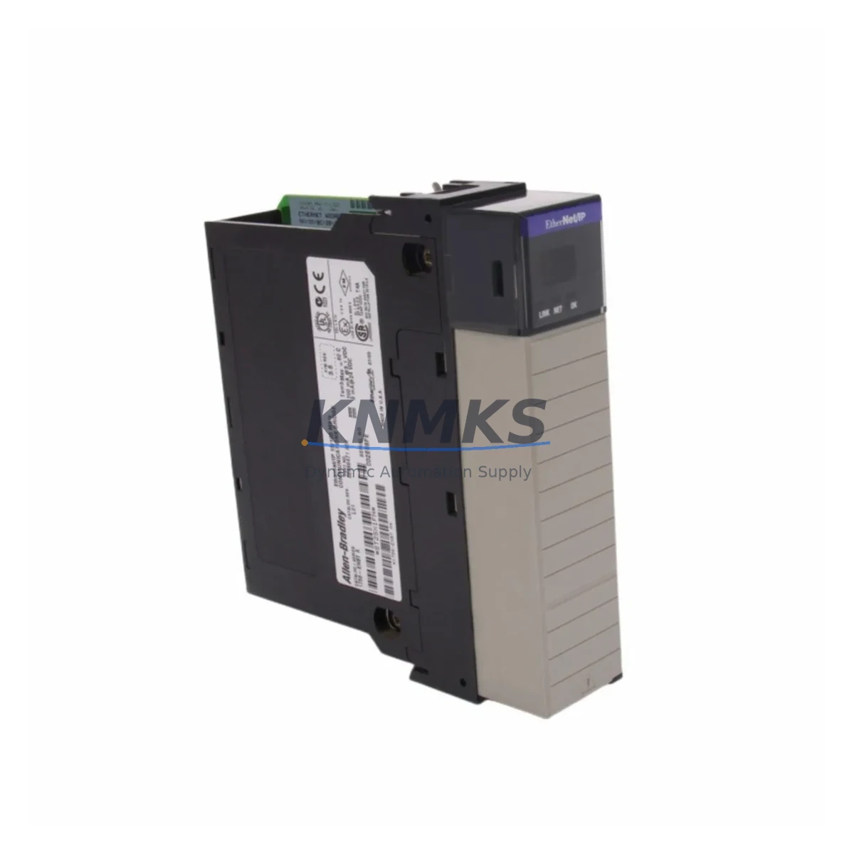
For systems using the 1756-OX8I in safety-adjacent or high-availability circuits, cross-reference the output assignments in RSLogix 5000 / Studio 5000 and confirm that the 1756-EN2T or 1756-EN2TR EtherNet/IP communication module is maintaining stable I/O connection. Communication faults can mask output module status and delay fault isolation. If the system includes a 1756-IB16 or 1756-IA16 digital input module for feedback confirmation of relay states, verify those input channels are reading correctly after the replacement.
In facilities running mixed I/O architectures, it is also advisable to inspect any 1492-IFM interface modules or terminal blocks used as wiring intermediaries between the 1756-OX8I and field devices. These components accumulate wear independently of the PLC module and are frequently overlooked during spare parts planning. Finally, confirm that the replacement module firmware revision is compatible with the existing controller firmware to avoid unexpected behavior after hot-swap or cold restart.
Site Replacement Workflow
Step 1 — Pre-Replacement Verification: Document the current I/O map and tag assignments for all 8 relay output channels. Export the Studio 5000 project file and note the module revision currently installed. Confirm the replacement 1756-OX8I matches the required catalog number and series letter.
Step 2 — Safe Isolation: De-energize field loads connected to the relay outputs. For isolated relay modules, each channel can be de-energized independently — use this to minimize production impact where possible. Follow site LOTO (Lockout/Tagout) procedures before removing the RTB.
Step 3 — Module Removal and Inspection: Remove the RTB first, then extract the 1756-OX8I from the chassis slot. Inspect the backplane connector and chassis slot for damage. Clean the slot if contamination is present.
Step 4 — Replacement Installation: Insert the new 1756-OX8I into the same chassis slot. Reconnect the RTB. The ControlLogix controller will automatically recognize the module if the configuration matches — no re-download is required in most cases.
Step 5 — Functional Verification: Force each output channel individually in Studio 5000 to confirm relay operation. Verify field device response for all 8 channels before returning the system to automatic mode.
This workflow supports legacy system life extension, reduces mean time to repair (MTTR), and maintains full compatibility with existing ControlLogix configurations — eliminating the need for costly system redesign or controller migration.
Spare Parts Support FAQ
Q1: Is the 1756-OX8I compatible with all ControlLogix 1756 chassis sizes?
Yes. The 1756-OX8I is compatible with all standard 1756 Series chassis, including the 1756-A4, 1756-A7, 1756-A10, 1756-A13, and 1756-A17. It occupies a single chassis slot and communicates over the standard ControlLogix backplane. Confirm the series letter of your existing module matches the replacement to ensure firmware compatibility.
Q2: How should I manage 1756-OX8I inventory for a multi-line facility?
For facilities with 3 or more ControlLogix systems, maintaining a minimum of 1–2 spare 1756-OX8I modules on-site is recommended. Relay output modules have a finite contact life cycle and are among the most frequently replaced I/O modules in high-cycle applications. Align your reorder point with annual maintenance schedules to avoid emergency procurement delays.
Q3: What testing is performed before shipment?
Each 1756-OX8I spare is functionally tested prior to shipment, including relay contact continuity verification, backplane communication check, and visual inspection of the RTB connector and module housing. Units are shipped with protective packaging to prevent ESD damage and physical shock during transit.
Q4: What does the support terms confirmed by quotation cover?
The support terms confirmed by quotation cover manufacturing defects and functional failures under normal operating conditions. It does not cover damage resulting from incorrect installation, overvoltage, or failure to follow Rockwell Automation’s published installation guidelines. Support requests are supported with direct technical assistance and priority replacement shipment.
© 2026 KNMKS. All rights reserved.
Original Source: https://knmks.com
Contact: admin@knmks.com | +86 18359268345
Product Identification
- Brand / Ecosystem
-
Allen-Bradley
Allen-Bradley - Model / Series
-
1756-OX8I
ControlLogix Series - Product Family
- PLCs & Controllers
- Availability Status
- Available on request after model and quantity confirmation
- Inquiry Type
- B2B RFQ, replacement inquiry and project spare-part request
- Pre-Quote Check
- Exact SKU, brand, series, quantity, nameplate photos and destination country are checked before quotation
System Path
Where this product fits in the KNMKS automation structure.
Specification & Inquiry Focus
- Control platform
- PLC, PAC and modular controllers
- Common needs
- CPU, rack, power and I/O expansion
- Project support
- Replacement, cabinet build and maintenance
Buyer Confirmation
Information KNMKS checks before replying.
- Exact model
- 1756-OX8I
- Brand / ecosystem
- Allen-Bradley
- Product family
- PLCs & Controllers
- Application note
- Replacement, maintenance, project build or spare-part list
- Useful photos
- Nameplate, installed unit, cabinet layout or connector side
- Delivery details
- Quantity, destination country and target schedule
Document Support
Files and notes can be confirmed during quotation.
- Product photos or nameplate confirmation when available
- Packing and delivery notes before quotation confirmation
- Support scope and delivery terms confirmed per inquiry
- Export document coordination for qualified B2B requests
Inquiry Support
- Model cross-checking before quotation
- CPU, power, rack and expansion module matching
- Support for replacement and project inquiry
What to Send Us
- Brand and exact model number: Allen-Bradley 1756-OX8I
- Quantity and required delivery time
- Application, replacement requirement or nameplate photo
- Destination country and shipping preference
RFQ Preparation
This is a product inquiry page built for RFQ communication.
Fast Model Check
Send this model to KNMKS for confirmation.
Include quantity, destination country and photos if this is a maintenance replacement. The inquiry will be saved with a reference number after submission.
Brand & Compatibility Note
KNMKS displays automation product information for well-known industrial brand ecosystems and compatible replacement references. Brand names are used for product identification and compatibility reference only; final availability and commercial terms are confirmed per quotation.
 Manufacturing
 Machine Tools
 Packaging
 Energy & Power
 HMI & Displays
 Servo Systems
 Variable Frequency Drives
 Sensors