
Overview
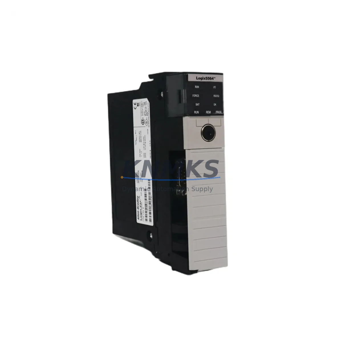
Allen-Bradley 1756-L64 Migration-Ready PLC Processor for Legacy Control Systems
The Allen-Bradley 1756-L64 (Logix5564) is a high-performance ControlLogix processor designed for mission-critical industrial automation environments. With 4 MB of user memory and full compatibility with the 1756 ControlLogix chassis backplane, this processor is a proven migration-ready replacement for aging Logix5550, Logix5555, and Logix5560 processors that have reached end-of-life or are no longer supported under Rockwell Automation’s standard product lifecycle. Whether you are managing a planned system upgrade or responding to an unplanned processor failure, the 1756-L64 provides a reliable, drop-in-compatible path forward with minimal disruption to existing ladder logic, function block diagrams, and structured text programs.
For facilities running legacy PLC-5, SLC 500, or early ControlLogix platforms, the 1756-L64 represents a well-supported migration target. Engineers undertaking a retrofit must verify several critical parameters before installation: the existing chassis slot count and backplane power budget (the 1756-PA75 or 1756-PB75 power supply must be confirmed to support the additional processor draw), terminal block wiring assignments on all installed I/O modules, and the firmware revision currently loaded on the replacement unit. Rockwell Automation recommends that the processor firmware be matched to the Studio 5000 Logix Designer project version to avoid compatibility warnings during program download.
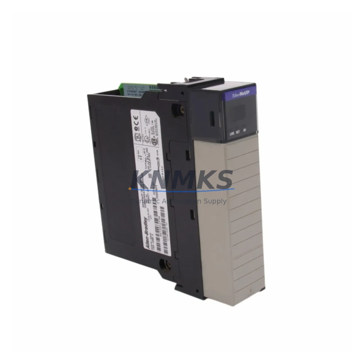
When replacing a 1756-L55 or 1756-L61 in an existing rack, engineers should also audit the 1756-ENBT or 1756-EN2T EtherNet/IP communication modules installed in the same chassis. The 1756-L64 supports both ControlNet (via 1756-CNB or 1756-CNBR bridge modules) and EtherNet/IP natively, but any existing DeviceNet links through a 1756-DNB scanner module must be re-verified for node address mapping after the processor swap. If the legacy system used a 1756-DHRIO module for Data Highway Plus or Remote I/O communication, those links should be tested under a controlled simulation before live cutover.
Migration Compatibility Table
| Parameter | Details |
|---|---|
| Replaces / Compatible With | 1756-L55, 1756-L61, 1756-L62, 1756-L63 (Logix5550–Logix5563) |
| Chassis Compatibility | All 1756 ControlLogix chassis (4, 7, 10, 13, 17-slot) |
| Backplane Interface | 1756 ControlLogix backplane — direct slot insertion, no adapter required |
| User Memory | 4 MB (Logix5564) |
| Communication Protocols | EtherNet/IP, ControlNet, DeviceNet (via bridge modules), DH+, Remote I/O |
| Programming Software | Studio 5000 Logix Designer v21 and above; RSLogix 5000 v16–v20 |
| Firmware Compatibility | Must match project revision; verify before download |
| Power Supply Requirement | Confirm 1756-PA75 / 1756-PB75 capacity before installation |
| Installation Footprint | Single slot, standard 1756 form factor |
| Retrofit Recommendation | Audit I/O module addresses, tag database, and HMI screen bindings before cutover |
| Commissioning Notes | Verify EtherNet/IP node addresses, ControlNet schedule, and DeviceNet node map post-swap |
| Support terms | support terms confirmed by quotation — functional test report available on request |
Retrofit Planning for Existing Automation Systems
A successful 1756-L64 retrofit begins well before the physical swap. Start by exporting the full ACD project file from the existing processor using RSLogix 5000 or Studio 5000 Logix Designer, and archive it to a secure location. Confirm that all 1756-IB16 digital input modules and 1756-OB16E digital output modules retain their slot assignments in the chassis, as the 1756-L64 will re-map I/O based on the slot configuration stored in the project file. Any mismatch between the physical rack layout and the project configuration will generate I/O faults on first scan.
For systems that include analog I/O — such as 1756-IF16 analog input or 1756-OF8 analog output modules — verify the channel scaling parameters and engineering unit conversions in the tag database before download. These values are not automatically migrated if the project was originally created on a significantly older firmware revision. Similarly, if the control cabinet includes a PanelView Plus HMI communicating over EtherNet/IP, the HMI screen bindings must be validated against the updated tag names in the new processor project. A tag rename or address change during migration will cause HMI display faults that require on-site correction.
Where the legacy system used a 1756-CNB ControlNet bridge module for distributed I/O across multiple racks, the ControlNet network schedule must be re-generated using RSNetWorx for ControlNet after the processor replacement. Failure to reschedule the network is one of the most common causes of post-retrofit communication faults. If the system also includes a 1756-DHRIO module for legacy PLC-5 or SLC 500 pass-through communication, confirm that the remote rack addresses and I/O chassis configurations are preserved in the new project. Signal isolators installed between field devices and I/O terminals should be inspected for loop power compatibility, particularly on 4–20 mA analog loops where the 1756-L64’s I/O modules may have slightly different input impedance characteristics than the legacy processor’s associated modules.
Downtime Control During System Migration
Minimizing unplanned downtime during a processor migration requires a structured cutover plan. Begin by scheduling the swap during a planned maintenance window, and prepare a rollback procedure that includes the original processor and a verified backup of the ACD project file. Before powering down the chassis, document the current I/O status, active faults, and any inhibited tasks in the processor. This snapshot serves as the baseline for post-cutover verification.
During the physical swap, the 1756-L64 should be inserted into the same chassis slot as the legacy processor. Power up the chassis without enabling outputs — most ControlLogix systems support a test mode or inhibited output configuration that allows the program to scan and verify I/O mapping before live control is restored. Download the project file, confirm that all I/O modules come online without faults, and verify that the EtherNet/IP connections to remote devices — including variable frequency drives, servo drives, and remote I/O adapters — are established correctly. Only after a full I/O scan with no faults should outputs be enabled and the system returned to automatic control.
For systems where continuous operation is critical, consider a parallel run strategy: install the 1756-L64 in an adjacent chassis slot (if available) and run the program in listen-only mode against the live I/O before the final cutover. This approach allows engineers to verify program logic, HMI bindings, and communication links without interrupting production. All units supplied are functionally tested prior to shipment, and a support terms confirmed by quotation cover any hardware defects identified after installation.
Retrofit Support FAQ
Q: Is the 1756-L64 a direct drop-in replacement for the 1756-L61 or 1756-L62?
A: Yes, the 1756-L64 uses the same 1756 ControlLogix backplane interface and single-slot form factor as the 1756-L61 and 1756-L62. The existing ACD project file can be downloaded directly after a firmware revision check. No chassis modification or wiring change is required for the processor itself, though I/O module slot assignments and communication module configurations must be verified before cutover.
Q: What firmware version is loaded on the unit, and how do I match it to my project?
A: Units are supplied with the firmware version specified at the time of order, or with the latest available revision if no version is specified. Firmware can be updated using ControlFLASH or ControlFLASH Plus. Always match the processor firmware to the Studio 5000 Logix Designer project version to avoid download errors. Contact our technical team before ordering if you require a specific firmware revision.
Q: How do I verify wiring compatibility when replacing a legacy processor?
A: The 1756-L64 does not have direct field wiring — all I/O connections are made through the installed 1756-series I/O modules in the chassis. Verify that each I/O module’s terminal block wiring matches the channel assignments in the project file. For analog modules, confirm loop power supply voltage and current draw. No rewiring of field devices is required if the I/O modules remain in their original chassis slots.
Q: What does the support terms confirmed by quotation cover, and is pre-shipment testing included?
A: All 1756-L64 units undergo functional testing prior to shipment, including power-on verification and basic communication checks. The support terms confirmed by quotation cover hardware defects under normal operating conditions. A test report is available on request. Units are shipped with ESD-protective packaging and include a 30-day return window for units that do not meet specification upon receipt.
© 2026 KNMKS. All rights reserved.
Original Source: https://knmks.com
Contact: admin@knmks.com | +86 18359268345
Product Identification
- Brand / Ecosystem
-
Allen-Bradley
Allen-Bradley - Model / Series
-
1756-L64
ControlLogix Series - Product Family
- PLCs & Controllers
- Availability Status
- Available on request after model and quantity confirmation
- Inquiry Type
- B2B RFQ, replacement inquiry and project spare-part request
- Pre-Quote Check
- Exact SKU, brand, series, quantity, nameplate photos and destination country are checked before quotation
System Path
Where this product fits in the KNMKS automation structure.
Specification & Inquiry Focus
- Control platform
- PLC, PAC and modular controllers
- Common needs
- CPU, rack, power and I/O expansion
- Project support
- Replacement, cabinet build and maintenance
Buyer Confirmation
Information KNMKS checks before replying.
- Exact model
- 1756-L64
- Brand / ecosystem
- Allen-Bradley
- Product family
- PLCs & Controllers
- Application note
- Replacement, maintenance, project build or spare-part list
- Useful photos
- Nameplate, installed unit, cabinet layout or connector side
- Delivery details
- Quantity, destination country and target schedule
Document Support
Files and notes can be confirmed during quotation.
- Product photos or nameplate confirmation when available
- Packing and delivery notes before quotation confirmation
- Support scope and delivery terms confirmed per inquiry
- Export document coordination for qualified B2B requests
Inquiry Support
- Model cross-checking before quotation
- CPU, power, rack and expansion module matching
- Support for replacement and project inquiry
What to Send Us
- Brand and exact model number: Allen-Bradley 1756-L64
- Quantity and required delivery time
- Application, replacement requirement or nameplate photo
- Destination country and shipping preference
RFQ Preparation
This is a product inquiry page built for RFQ communication.
Fast Model Check
Send this model to KNMKS for confirmation.
Include quantity, destination country and photos if this is a maintenance replacement. The inquiry will be saved with a reference number after submission.
Brand & Compatibility Note
KNMKS displays automation product information for well-known industrial brand ecosystems and compatible replacement references. Brand names are used for product identification and compatibility reference only; final availability and commercial terms are confirmed per quotation.
 Manufacturing
 Machine Tools
 Packaging
 Energy & Power
 HMI & Displays
 Servo Systems
 Variable Frequency Drives
 Sensors