
Overview
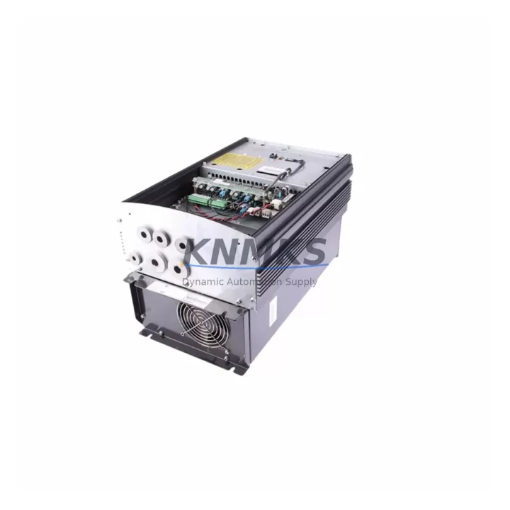
ABB ACS60100203 Migration-Ready VFD for Legacy Control Systems
The ABB ACS60100203 is a migration-ready variable frequency drive engineered as a verified drop-in replacement for legacy ACS600 series drives deployed across industrial motor control, pump, fan, compressor, and conveyor applications. As ABB progressively phases out ACS600 platform support and spare parts availability narrows, engineering teams managing aging control cabinets face increasing pressure to source pre-tested replacement units that preserve existing wiring topology, maintain communication protocol continuity, and eliminate unplanned downtime during changeover. The ACS60100203 addresses each of these concerns with a warehouse-stocked unit backed by a support terms confirmed by quotation and multi-region dispatch capability.
Before initiating a drive replacement, engineers must confirm several critical parameters: input power supply voltage and phase configuration, output current rating relative to motor nameplate data, DC bus capacitor condition in the existing cabinet, and the terminal block layout on the existing drive chassis. The ACS60100203 retains the standard ACS600 terminal arrangement, which significantly reduces rewiring time during scheduled outages. Teams should verify that existing cable cross-sections and ferrule types are compatible with the replacement unit’s terminal torque specifications before energizing.
Communication protocol continuity is a frequent concern during ACS600 replacements. The ACS60100203 supports the DDCS fiber-optic link used in legacy ABB Master/Follower configurations, as well as fieldbus adapter slots compatible with PROFIBUS-DP, Modbus RTU, and DeviceNet modules. If the existing system uses an NPBA-12 PROFIBUS adapter or an NMBA-01 Modbus adapter mounted on the original drive, these adapters can typically be remounted on the ACS60100203 without firmware reconfiguration, provided the adapter firmware version is compatible. Teams should retrieve the existing drive’s parameter backup using DriveWindow or DriveStudio before removal — this backup is essential for restoring motor control parameters, speed reference scaling, and PID loop tuning values on the replacement unit.
Rack and cabinet space confirmation is a prerequisite for any ACS600-series replacement. The ACS60100203 shares the R6 frame size footprint with the majority of ACS600 units in its power range, allowing direct panel cutout reuse in most installations. Engineers should also confirm that existing input fusing, main contactor rating, and EMC filter specifications remain within the replacement unit’s input requirements — particularly in installations where the original drive was paired with an ABB ACF-type input filter or a du/dt output filter protecting long motor cable runs.
For systems where the ACS60100203 interfaces with an ABB AC500 PLC or a third-party SCADA system via hardwired analog I/O, teams should verify the analog reference signal range (0–10 V or 4–20 mA) and confirm that existing AI/AO terminal wiring matches the replacement drive’s default parameter set. In multi-drive installations, the ACS60100203 can participate in the same Master/Follower torque-sharing configuration as the original ACS600 unit, provided the DDCS ring topology and fiber cable lengths are within specification. Where the control system includes an ACS600 Application Program running on the drive’s internal application module, the application program must be re-uploaded and validated after replacement — this step is frequently overlooked and is a common cause of post-replacement commissioning delays.
HMI screen updates are often required following an ACS600 drive replacement. If the existing HMI — whether an ABB CP600 operator panel, a Siemens TP700 Comfort, or a third-party SCADA terminal — displays drive status via parameter read/write over PROFIBUS or Modbus, the parameter address mapping must be verified against the replacement drive’s parameter list. In most ACS600 replacements, parameter numbering is preserved, but teams should cross-reference the ACS60100203 firmware parameter list against the HMI tag database before go-live to avoid alarm masking or incorrect status display.
Migration Compatibility Table
| Parameter | Legacy ACS600 | ACS60100203 (Replacement) | Action Required |
|---|---|---|---|
| Frame Size | R6 | R6 | No panel modification required |
| Input Voltage | 380–500 V AC, 3-phase | 380–500 V AC, 3-phase | Verify supply voltage tolerance |
| Communication | DDCS fiber / PROFIBUS-DP / Modbus RTU | DDCS fiber / PROFIBUS-DP / Modbus RTU | Reuse existing adapter; verify firmware |
| Terminal Layout | Standard ACS600 terminal block | Compatible terminal block | Verify cable cross-section and torque spec |
| Parameter Backup | DriveWindow / DriveStudio export | DriveWindow / DriveStudio import | Backup before removal; restore after install |
| Fieldbus Adapter | NPBA-12 / NMBA-01 (existing) | Compatible adapter slot | Remount existing adapter; verify firmware version |
| Application Program | ACS600 Application Module | Re-upload required | Upload and validate before energizing motor |
| HMI Parameter Mapping | Existing PROFIBUS/Modbus tag database | Cross-reference required | Validate HMI tags against ACS60100203 parameter list |
| Support terms | OEM support ended | support terms confirmed by quotation | Covered from date of dispatch |
| Pre-Shipment Test | N/A | Full functional test completed | Test report available on request |
Retrofit Planning for Existing Automation Systems
A successful ACS600 retrofit begins with a complete audit of the control cabinet before any hardware is removed. Engineering teams should document the existing wiring schedule, photograph all terminal connections, and export the drive parameter set using DriveWindow or DriveStudio. In cabinets where the ACS600 drive is paired with an ABB IOEC I/O extension module for remote digital and analog I/O, the IOEC module’s DDCS address and channel assignments must be recorded — these settings are not stored in the drive parameter backup and must be manually re-entered after replacement.
Power supply integrity is a critical pre-replacement check. The ACS60100203 requires a stable 24 V DC auxiliary supply for the control board; teams should verify that the existing 24 V SMPS in the cabinet has sufficient current headroom after accounting for all connected I/O modules, relay outputs, and communication adapters. In older installations, the 24 V supply may be shared with an ABB RDCO-01 DDCS communication module or an RAIO-01 analog I/O extension — both of which draw additional current that must be factored into the supply budget.
For installations where the ACS60100203 controls a motor via a long cable run exceeding 50 meters, the existing du/dt output filter or sine filter must be retained and reconnected to the ACS60100203 output terminals. Removing or bypassing the output filter during replacement is a common commissioning error that can cause motor insulation stress and premature bearing failure. Teams should also confirm that the existing motor thermistor (PTC) wiring is connected to the correct thermistor input on the replacement drive and that the thermistor protection function is enabled in the drive parameters.
In multi-drive systems where the ACS60100203 operates alongside other ACS600 units in a Master/Follower torque-sharing configuration, the replacement drive must be assigned the correct DDCS node address and Master/Follower role before the system is restarted. The DDCS fiber ring must be inspected for damaged connectors or excessive bend radius before reconnection — fiber link errors are a frequent cause of Master/Follower synchronization failures after drive replacement. Where the system also includes an ABB ACS800 drive in a mixed-generation installation, teams should verify that the DDCS protocol version is compatible across all nodes in the ring.
Downtime Control During System Migration
Minimizing downtime during an ACS600 drive replacement requires a structured pre-outage preparation protocol. All parameter backups, wiring photographs, HMI tag lists, and fieldbus configuration files should be prepared and verified at least 48 hours before the planned outage window. The replacement ACS60100203 unit should be bench-tested with a motor simulator or a small test motor before installation to confirm that the unit powers up correctly, the control board initializes without fault codes, and the communication adapter responds on the fieldbus network.
During the outage, the recommended sequence is: isolate and lock out the incoming supply, discharge the DC bus (minimum 5 minutes after isolation), disconnect and label all power and control cables, remove the legacy drive, install the ACS60100203, reconnect power and control cables in reverse order, restore the parameter backup, re-upload the application program if applicable, and perform a no-load motor run test before returning the drive to automatic control. Teams should resist the temptation to skip the no-load test — parameter scaling errors and analog reference wiring mistakes are most easily identified at this stage, before the motor is coupled to the load.
Where the process cannot tolerate a full outage, a bypass contactor strategy can be implemented to maintain motor operation on direct-on-line (DOL) starting while the drive is replaced. This approach requires that the existing motor starter circuit includes a bypass contactor and that the process can tolerate the step-change in motor speed during the transition from DOL to VFD control. The bypass strategy is particularly effective in pump and fan applications where the process can absorb a brief period of uncontrolled flow before the replacement drive assumes speed reference control.
Post-replacement, teams should monitor the ACS60100203 for the first 72 hours of operation, logging any fault codes, thermal warnings, or communication errors. The drive’s event log should be reviewed at the end of the first production shift to confirm that no intermittent faults occurred during normal operation. All commissioning records, parameter printouts, and test results should be archived in the plant maintenance management system for future reference.
Retrofit Support FAQ
Q1: Is the ACS60100203 a direct drop-in replacement for all ACS600 R6 frame drives?
The ACS60100203 is compatible with the majority of ACS600 R6 frame installations in the same power range. Teams should verify the exact input voltage, output current rating, and frame variant (standard or IP54 enclosure) against the nameplate data of the unit being replaced. In most cases, the terminal layout, mounting footprint, and communication adapter slots are directly compatible, allowing replacement without panel modification.
Q2: Can I reuse the existing PROFIBUS or Modbus adapter from the original ACS600 drive?
In most cases, yes. The NPBA-12 PROFIBUS-DP adapter and NMBA-01 Modbus RTU adapter used on ACS600 drives are compatible with the ACS60100203 adapter slot. Before remounting, verify that the adapter firmware version is compatible with the replacement drive’s firmware. If the adapter firmware requires an update, this can be performed using DriveWindow before installation.
Q3: What pre-shipment testing is performed on the ACS60100203?
Each ACS60100203 unit undergoes a full functional test prior to dispatch, including power-on verification, control board initialization check, analog and digital I/O function test, and communication adapter response test where applicable. A test report is available on request. All units are dispatched with a support terms confirmed by quotation covering manufacturing defects and functional failures under normal operating conditions.
Q4: What is the typical lead time and stock availability for the ACS60100203?
The ACS60100203 is maintained in multi-region stock to support emergency replacement and scheduled outage requirements. Standard dispatch is within 2–5 business days for in-stock units. For urgent requirements, same-day or next-day dispatch may be available depending on the destination region. Contact the sales team to confirm current stock levels and lead time for your location.
© 2026 KNMKS. All rights reserved.
Original Source: https://knmks.com
Contact: admin@knmks.com | +86 18359268345
Product Identification
- Brand / Ecosystem
-
ABB
ABB - Model / Series
-
ACS60100203
Legacy Series - Product Family
- Variable Frequency Drives
- Availability Status
- Available on request after model and quantity confirmation
- Inquiry Type
- B2B RFQ, replacement inquiry and project spare-part request
- Pre-Quote Check
- Exact SKU, brand, series, quantity, nameplate photos and destination country are checked before quotation
System Path
Where this product fits in the KNMKS automation structure.
Specification & Inquiry Focus
- Drive range
- AC drives, VFDs and accessories
- Common needs
- Voltage, kW/HP and load type
- Project support
- Motor control, energy saving and spares
Buyer Confirmation
Information KNMKS checks before replying.
- Exact model
- ACS60100203
- Brand / ecosystem
- ABB
- Product family
- Variable Frequency Drives
- Application note
- Replacement, maintenance, project build or spare-part list
- Useful photos
- Nameplate, installed unit, cabinet layout or connector side
- Delivery details
- Quantity, destination country and target schedule
Document Support
Files and notes can be confirmed during quotation.
- Product photos or nameplate confirmation when available
- Packing and delivery notes before quotation confirmation
- Support scope and delivery terms confirmed per inquiry
- Export document coordination for qualified B2B requests
Inquiry Support
- Input/output voltage and kW/HP confirmation
- Energy-saving motor control inquiry
- Accessory and spare-unit support
What to Send Us
- Brand and exact model number: ABB ACS60100203
- Quantity and required delivery time
- Application, replacement requirement or nameplate photo
- Destination country and shipping preference
RFQ Preparation
This is a product inquiry page built for RFQ communication.
Fast Model Check
Send this model to KNMKS for confirmation.
Include quantity, destination country and photos if this is a maintenance replacement. The inquiry will be saved with a reference number after submission.
Brand & Compatibility Note
KNMKS displays automation product information for well-known industrial brand ecosystems and compatible replacement references. Brand names are used for product identification and compatibility reference only; final availability and commercial terms are confirmed per quotation.
 Manufacturing
 Machine Tools
 Packaging
 Energy & Power
 PLCs & Controllers
 HMI & Displays
 Servo Systems
 Sensors