
Overview
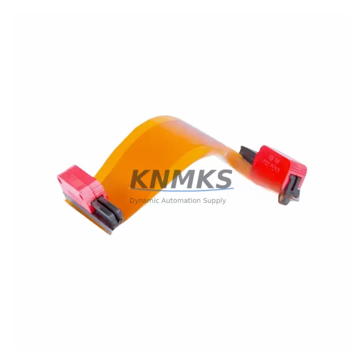
ABB 1948502A0340 Migration-Ready Expander Bus Cable for Legacy Control Systems
The ABB 1948502A0340 is a factory-specification expander bus cable engineered for the AC500 programmable logic controller platform. As legacy AC500 installations approach end-of-support milestones, engineering teams managing scheduled outages, emergency replacements, and phased control-cabinet upgrades increasingly rely on verified, migration-ready spare parts to maintain production continuity. This cable provides a direct, drop-in replacement path for aging or failed expander bus assemblies without requiring firmware changes, rack redesign, or PLC program modification.
The 1948502A0340 connects the AC500 CPU module — typically a PM571, PM581, or PM591 — to downstream I/O expansion modules mounted on the same TB511 or TB521 terminal base assembly. Its shielded construction and impedance-matched connectors preserve signal integrity across the full AC500 communication bus, ensuring deterministic scan-cycle performance even in electrically noisy industrial environments such as motor-drive panels, switchgear rooms, and process-control cabinets.
When planning a retrofit or spare-parts replenishment, engineers must verify several critical parameters before installation. Power supply capacity at the rack level — typically provided by a CP502 or CP503 power supply module — must be confirmed against the aggregate current draw of all connected I/O modules. Terminal wiring on the TB511 base must be inspected for correct torque and conductor cross-section before the new cable is seated. Backplane connector alignment on both the CPU side and the expansion module side should be checked visually to prevent pin damage during insertion. Module addressing — set via DIP switch or software configuration in Automation Builder — must match the address map defined in the existing PLC program to avoid I/O mapping conflicts after restart. HMI screen tag bindings referencing the affected I/O channels should be validated in the SCADA or Panel Builder project before the system is returned to service.
Communication link integrity is equally important. In AC500 installations that use the CS31 fieldbus or PROFIBUS DP for distributed I/O, the expander bus cable replacement must not disturb the master-slave address table or the baud-rate configuration stored in the CPU. Where Modbus RTU or Modbus TCP is used for upstream SCADA connectivity, the communication parameters in the CP600 HMI or third-party supervisory system should be verified post-replacement to confirm that no timeout or framing errors have been introduced.
Installation space confirmation is a practical prerequisite in dense control cabinets. The 1948502A0340 cable routing must clear adjacent components — including the SD card slot on the CPU module, the USB programming port used with the PS501 Control Builder Plus cable, and any adjacent TU515 or TU516 I/O terminal units. Firmware version compatibility between the CPU and expansion modules should be confirmed in the AC500 firmware release notes; mismatched firmware versions can cause bus initialization failures that are difficult to diagnose without a laptop running Automation Builder connected via the programming port.
Pre-shipment testing is performed on every unit before dispatch. Each 1948502A0340 cable is verified for connector continuity, shield integrity, and dimensional conformance to ABB factory specifications. A support terms confirmed by quotation cover manufacturing defects and connector failure under normal operating conditions. Multi-region stock is maintained to support both emergency same-day dispatch and scheduled maintenance windows, minimizing the risk of extended downtime caused by parts unavailability.
Migration Compatibility Table
| Parameter | Specification / Recommendation |
|---|---|
| Compatible CPU Modules | ABB AC500: PM571, PM581, PM591, PM592, PM595 |
| Compatible Terminal Bases | TB511, TB521 (AC500 standard rack) |
| Compatible I/O Expansion Modules | DC532, DC522, AI531, AO523, DI524 and AC500 I/O series |
| Communication Bus | AC500 internal expansion bus (proprietary); CS31 / PROFIBUS DP unaffected |
| Installation Requirement | Power-off installation; confirm rack power budget before re-energizing |
| Firmware Compatibility | Compatible with AC500 firmware V2.x and V3.x; verify CPU and I/O module firmware match |
| Replacement Recommendation | Direct drop-in replacement; no program modification required |
| Commissioning Focus | I/O address map verification, HMI tag validation, communication link test |
| Origin | Germany (DE) |
| Support terms | 12 months from shipment date; covers manufacturing defects and connector failure |
Retrofit Planning for Existing Automation Systems
A structured retrofit plan reduces risk and shortens the commissioning window when replacing the 1948502A0340 in an operating facility. Begin by documenting the current rack layout: record the slot positions of all I/O modules, the address assignments configured in Automation Builder, and the wiring schedule for each TU515 or TU516 terminal unit. This documentation serves as the baseline for post-replacement verification and is essential if the HMI project — typically running on a CP600 or CP635 panel — needs to be updated to reflect any channel reassignments.
Power budget analysis is the next critical step. The CP502 or CP503 power supply module feeding the rack must have sufficient headroom to support all connected modules after the cable replacement. If the existing power supply is operating near its rated output, consider replacing it concurrently with the bus cable to avoid nuisance trips during the commissioning phase. Signal isolators installed between the AC500 I/O modules and field instruments — particularly on analog input channels connected to 4–20 mA transmitters — should be checked for correct loop power configuration before the system is restarted.
Programming cable access is a practical consideration during commissioning. The PS501 Control Builder Plus USB programming cable or the TK501 Ethernet programming adapter should be connected to the CPU before power-up so that the Automation Builder diagnostic screen can be monitored in real time during bus initialization. Any I/O module that fails to appear on the expansion bus after power-up should be investigated for address conflict, firmware mismatch, or connector seating issues before the system is released to production.
For installations that include a CS31 remote I/O network, the CS31 master configuration stored in the CPU must be verified to confirm that the expansion bus replacement has not altered the master’s polling table. Similarly, if a CI590 PROFIBUS DP communication interface module is installed in the rack, its GSD file configuration in the PROFIBUS master should be checked to confirm that the module’s station address and I/O byte count remain consistent with the pre-replacement configuration.
Downtime Control During System Migration
Minimizing unplanned downtime during an expander bus cable replacement requires a disciplined sequence of pre-outage, outage, and post-outage activities. Before the maintenance window opens, upload the current PLC program from the CPU using Automation Builder and save a timestamped backup to a secure network location. Export the HMI project from the CP600 or CP635 panel and verify that the backup compiles without errors in Panel Builder 600. Photograph the existing cable routing and connector orientation to guide reinstallation.
During the outage, follow a controlled power-down sequence: disable field outputs, set the CPU to STOP mode via Automation Builder, then remove rack power from the CP502 or CP503 supply. Replace the 1948502A0340 cable, verify connector seating on both ends, and restore rack power. Monitor the Automation Builder diagnostic screen during CPU startup to confirm that all I/O modules enumerate correctly on the expansion bus before switching the CPU to RUN mode.
Post-replacement verification should include a full I/O force test on critical channels, a communication link check on all PROFIBUS DP and CS31 segments, and a functional test of all HMI alarm and control screens. Document the replacement in the site maintenance log with the cable serial number, installation date, and technician sign-off. This record supports the support terms confirmed by quotation claim process and provides traceability for future audits.
For facilities that cannot tolerate a full production stop, a hot-standby AC500 rack pre-wired with the replacement cable can be prepared offline and swapped in as a complete assembly, reducing the live outage to the time required for a controlled CPU switchover and I/O reconnection.
Retrofit Support FAQ
Q1: Is the ABB 1948502A0340 a direct replacement for the original factory cable in all AC500 rack configurations?
Yes. The 1948502A0340 is manufactured to ABB factory specifications and is compatible with all standard AC500 rack configurations using TB511 and TB521 terminal bases. No program modification or firmware update is required for a like-for-like replacement. Verify the slot count and module types in your rack against the AC500 system manual before installation to confirm that no address reassignment is needed.
Q2: What commissioning steps are required after installing the replacement cable?
After power-up, connect a laptop running Automation Builder via the PS501 USB programming cable or TK501 Ethernet adapter and verify that all I/O modules appear on the expansion bus with their correct addresses. Perform a forced I/O test on critical digital and analog channels. Check the CP600 or CP635 HMI for alarm-free operation and confirm that all PROFIBUS DP and CS31 communication links are active before releasing the system to production.
Q3: How is the cable tested before shipment, and what does the support terms confirmed by quotation cover?
Every 1948502A0340 unit undergoes pre-shipment continuity testing, shield integrity verification, and dimensional inspection against ABB factory tolerances. The support terms confirmed by quotation cover manufacturing defects, connector failure, and shield discontinuity under normal operating conditions. Support requests require the original shipment documentation and a description of the failure mode; replacement units are dispatched from multi-region stock to minimize lead time.
Q4: Can this cable be used in a phased migration where only part of the AC500 rack is being upgraded?
Yes. The 1948502A0340 supports phased migrations where the CPU and some I/O modules are retained while others are replaced or relocated. Ensure that the firmware versions of retained modules are compatible with any newly installed modules, and verify that the Automation Builder hardware configuration reflects the post-migration rack layout before downloading the updated program to the CPU.
© 2026 KNMKS. All rights reserved.
Original Source: https://knmks.com
Contact: admin@knmks.com | +86 18359268345
Product Identification
- Brand / Ecosystem
-
ABB
ABB - Model / Series
-
1948502A0340
AC500 Series - Product Family
- Cables & Connectors
- Availability Status
- Available on request after model and quantity confirmation
- Inquiry Type
- B2B RFQ, replacement inquiry and project spare-part request
- Pre-Quote Check
- Exact SKU, brand, series, quantity, nameplate photos and destination country are checked before quotation
System Path
Where this product fits in the KNMKS automation structure.
Specification & Inquiry Focus
- Cable range
- Sensor, servo, network and circular connectors
- Common needs
- Length, pin count, shielding and plug type
- Project support
- Machine wiring and installation kits
Buyer Confirmation
Information KNMKS checks before replying.
- Exact model
- 1948502A0340
- Brand / ecosystem
- ABB
- Product family
- Cables & Connectors
- Application note
- Replacement, maintenance, project build or spare-part list
- Useful photos
- Nameplate, installed unit, cabinet layout or connector side
- Delivery details
- Quantity, destination country and target schedule
Document Support
Files and notes can be confirmed during quotation.
- Product photos or nameplate confirmation when available
- Packing and delivery notes before quotation confirmation
- Support scope and delivery terms confirmed per inquiry
- Export document coordination for qualified B2B requests
Inquiry Support
- Cable length and connector type confirmation
- Servo, sensor and network cable inquiry
- Accessory kits for installation teams
What to Send Us
- Brand and exact model number: ABB 1948502A0340
- Quantity and required delivery time
- Application, replacement requirement or nameplate photo
- Destination country and shipping preference
RFQ Preparation
This is a product inquiry page built for RFQ communication.
Fast Model Check
Send this model to KNMKS for confirmation.
Include quantity, destination country and photos if this is a maintenance replacement. The inquiry will be saved with a reference number after submission.
Brand & Compatibility Note
KNMKS displays automation product information for well-known industrial brand ecosystems and compatible replacement references. Brand names are used for product identification and compatibility reference only; final availability and commercial terms are confirmed per quotation.
 Manufacturing
 Machine Tools
 Packaging
 Energy & Power
 PLCs & Controllers
 HMI & Displays
 Servo Systems
 Variable Frequency Drives