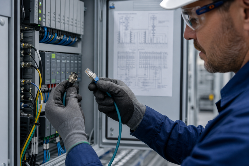
Replacing an industrial automation cable or connector is not only a matter of matching a part number. A cable can carry power, feedback, safety signals, or network traffic, and a connector can define pin assignment, shielding, coding, and environmental protection. A visually similar replacement may still create intermittent faults, communication errors, or an installation problem.
For a reliable industrial cable replacement RFQ, start with the installed system and the cable’s actual role. The model printed on a jacket or connector is useful, but it should be checked together with the equipment interface, wiring documentation, connector keying, length, and operating environment.
1. Identify the cable role before comparing part numbers
First classify the cable as a power cable, motor or servo cable, encoder or feedback cable, discrete I/O cable, safety circuit cable, or industrial communication cable. The role determines which electrical and mechanical characteristics are critical. A cable used for a VFD motor connection has different requirements from an Ethernet patch lead or a low-level analog signal cable.
Record the equipment at both ends of the connection. For example, note the PLC, remote I/O station, HMI, drive, servo motor, encoder, switch, junction box, or field device. This system context helps distinguish a cable with a similar connector but a different signal assignment. You can review the KNMKS Cables & Connectors category and the product directory as starting points for an inquiry.
2. Confirm connector size, coding, and pinout
Connector appearance is not enough. Confirm the connector family, number of contacts, gender, keying or coding, locking method, and termination style. Industrial installations may use M8 or M12 connectors, RJ45 variants, D-sub connectors, terminal blocks, circular connectors, or manufacturer-specific interfaces. Even within one family, A-coded, B-coded, D-coded, and X-coded versions can serve different functions.
Compare the pinout from the installed drawing, the equipment manual, and the connector markings. Check whether unused pins, drain wires, shield contacts, or jumper links are present. A replacement with the same number of contacts can still be unsuitable if the pin order or coding is different. Include clear photos of both ends, the keyway, labels, and any visible part number in the RFQ.
3. Check signal, power, and network requirements
For power and motor cables, record rated voltage, current, conductor size, number of cores, temperature rating, and grounding arrangement. For encoder or feedback cables, note the feedback type, pair construction, shielding, and connector assignment. For analog or low-level signals, identify the signal type and whether the cable is twisted, shielded, or separated from high-energy circuits.
For industrial Ethernet and fieldbus applications, document the protocol, cable category, impedance, pair count, shielding construction, connector type, and required transmission speed. Siemens cabling documentation explains why cable construction and connector selection belong together in an industrial network design. Phoenix Contact also separates data connectors, signal cables, power cables, and circular connector families in its product documentation. These references are useful for terminology and selection context, but the installed system documentation remains the final compatibility reference.
For reference, see Siemens cabling technology documentation and the Phoenix Contact circular connector overview. If your requirement involves a Siemens ecosystem, the KNMKS Siemens brand reference can help organize the inquiry before model confirmation.
4. Verify shielding, grounding, and EMC details
Shielding is part of the signal path and installation method, not a cosmetic feature. Confirm whether the original cable uses an overall braid, foil, individually shielded pairs, a drain wire, or a shielded backshell. Check how the shield is bonded at each end and whether the connector provides a 360-degree shield termination.
Also record the routing environment. Power, motor, and communication cables may require separation or a specific routing method to limit interference. A cable that works on a bench may behave differently in a cabinet or cable carrier if its shielding, bend radius, or termination is changed.
5. Confirm length and mechanical installation conditions
Measure the installed length and note whether the cable is fixed, flexing, dragged in a carrier, or exposed to repeated torsion. Record the minimum bend radius, connector orientation, jacket material, temperature range, oil or chemical exposure, vibration, ingress protection requirement, and available clearance. A longer cable is not automatically an equivalent cable if voltage drop, signal timing, attenuation, or mechanical routing changes.
Photograph the complete route where possible. Include the cabinet entry, strain relief, connector lock, cable carrier, and the space around the mating equipment. This is especially important when the replacement will be installed during a maintenance window with limited access.
6. Prepare a useful RFQ checklist
- Exact manufacturer name and complete cable or connector model.
- Photos of both ends, labels, keying, and the installed connection.
- Equipment and interface at each end, including drive, PLC, HMI, I/O, motor, encoder, or switch.
- Signal or power role, protocol, voltage, current, speed, and shielding requirement.
- Length, connector orientation, bend radius, flexing condition, temperature, and installation environment.
- Quantity, target delivery country, project or replacement use, and required timing.
If the model is unclear, send the nameplate or connector photo rather than guessing from the housing shape. For comparison context, this ABB programming cable reference shows why the application and system role matter alongside the model number.
Final compatibility gate
Before approving an industrial cable or connector replacement, confirm five things together: the system interface, the pinout and coding, the electrical or network specification, the shielding and grounding method, and the mechanical environment. If any one of these remains uncertain, the fastest next step is a documented model check with photos and installation details.
KNMKS supports model-based industrial automation inquiries for cables, connectors, and related control components. Send the exact reference, quantity, destination country, and available photos for an RFQ review focused on compatibility rather than appearance alone.
Related Product Paths